With the chassis nearly completed, except some minor J things like an
incomplete steering box and no front shock absorbers, I can start thinking
about putting the engine together. I
dont expect it to be an easy task, because of the lack of
documentation, but mostly because I did not took it apart myself
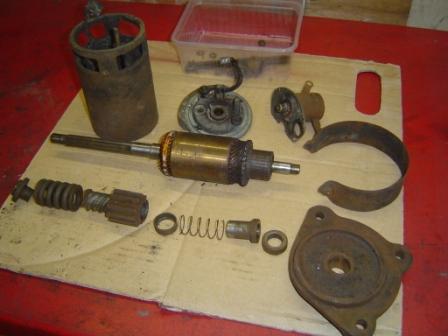
I thought it would be a good idea to start with some parts that come
aside, but are necessary in the whole picture. The starter and the dynamo
needed some good attention, as did the petrol pump. They all looked if as they
have been lying in a barn for more than a quart of a century, and in fact they
did
So I started with the dynamo, took it carefully apart, cleaned
everything and checked the state of the different parts. The brushes where
perfect, and the anchor was made as new on the lathe. To be sure it can go on
for another 25 years, I also made a new bronze end bush. I will be 85 by then,
so that must be sufficient J. Then
I put the whole thing back together, and tested it simply by giving it power so
it had to act as an electric engine. Result: 100%.
Than the starter, same procedure, same state. Just the starter relay,
in fact a cable operated mechanical part that makes the connection between the
main power cable and the starter. That needed a lot of internal cleaning, because
dirt and corrosion has took over from clean copper connections. But there is
nothing that a good wire brush cant clean, especially if it is mounted on a
drill. The test was also 100%, and I was happy J. The petrol pump also just needed a good
cleaning in and out, a test, and OK. This must have been the easy part, it was
going to well.
Then came the serious work
The drive line of the engine was already
done by the previous owner Jean. But to be sure what was undertaken, I phoned
him. No worries he assured me, the block had a rebore by a professional . They
fitted new pistons, the crank was regrinded, and they added all new bearing
shells. So now it was my turn.
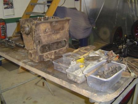
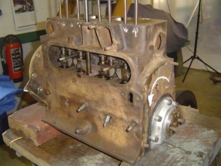
Before starting to put things together, I cleaned the whole inside of
the block, and gave the oil canals a good flush with pressed air. Than I cleaned
the whole pile of parts that came out of the boxes, and laid them all out on display,
just to see what Ive got and what probably comes where. It looks pretty
complete
The two aluminium blocks that have to close the underside of the engine,
once the crank is in, had damaged tread where the bolts of the oil pan have to
come. I decided to go for the easy solution, Helicoil. So I put an oversize
coil in it with inside tread of M8, very similar on the original BSF ¼ tread.
Easy and a perfect, with an even stronger tread than the original one in the
aluminium. I bought four new M8 bolts with the same length as the BSF ones, and
ready!
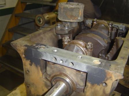
Then came the camshaft in the block, and I put the gallery with the cam
followers in, just to have a better sight on the future valve movement
according to the crankshaft and piston movements. The two sprockets came on
their correct lined spot, and then while turning the camshaft by hand as a
test, I had a what is this moment
The number 1 and 4 pistons where on TDC, and by turning the camshaft
further after the compression stroke on nr. 1, the outlet valve normally
opens. Here the inlet did, so the whole process of filling compression work
and exhaust has just begun. I tried and
looked, and tried and looked, and came to the conclusion that the piston on the
flywheel side is in fact the nr 1 piston, usually that is the nr. 4
And by
looking at the turning direction of the starter, I saw that the engine runs clockwise, looked
at it from the front. Now everything was clean as a whistle, but it took me
some time to find out.
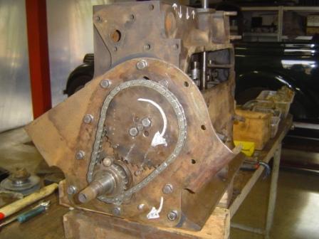
So the front plate came on, and the camshaft and sprockets came definitely
on their spot, provided with and a brand new timing chain and tensioner. On the
back the rear aluminium crankshaft housing was put in place, and carefully
measured out to be perfect in the centre. Very important, because otherwise the
oil thrower cannot work as it should. And, you have a high risk on damaging the
aluminium housing with real bad oil leaks as a result.
 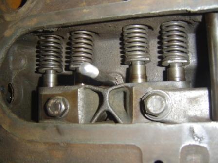
Than the battle with the springs that come on the underside of the valve
pushrods began. It is a strange construction with springs on the underside of
the pushrods, where they adapt to the cam followers. I never seen that system before,
and honestly I dont see the purpose of it. But it is British, isnt it J.
So I tried to put the blocking scales in - they have to keep the springs
on tension - but needed a few more extra
small hands, and a lot of extra space to do so. I even made some sort of a
tool, but nothing helped. So the gallery with the cam followers came back out
to provide the extra space. And then with the help of my son we put the springs
in, put the scales on their spot, and pushed the whole thing completely to the
upper side of the block.
Then we blocked the pushrods on the top side with some locking pliers,
keeping everything at maximum pressure
and out of the way to refit the gallery. Simple and straightforward, but you
need to figure it out. Than the drive shaft for the distributor came in place,
pointing at the nr. 1 piston, and completely below assuring the drive for the
oil pump. Then I noticed that the distributor is not the original one, it fits
in the housing, but has a completely different fitting to the drive shaft.
Hopefully I can make a conversion dog drive, well see about that later...
 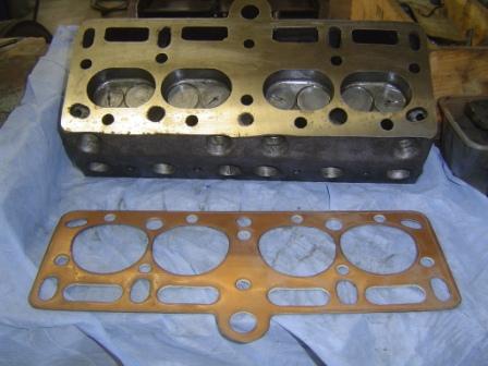
Then the repaired cylinder head went up, using a new custom made head
gasket. It was tightened at 40 lbs, and following the tightening sequence I
found on the website of the Morgan club of Australia.
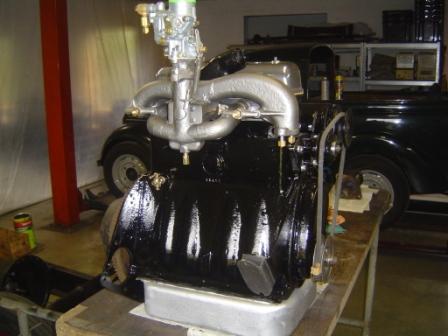
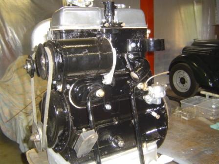
Then I painted the engine , and George told me it has to be in black, so
I did. By now I hope that he meant the colour... J J J. Afterwards
I added the oil pan, and started to bolt on all the side parts on the engine.
Surely it looks nice, lets hope it will turn even better
So now I just had to figure out how the front dynamo bracket comes on
the block, and make one for the rear side of the dynamo (a missing part).
Then the oil filter will be a real challenge, because the original AC
ZR1 bypass filter is no longer available. So I have to make a conversion plate
to adapt an modern screw on type of filter, and then I have to make and couple
all the oil lines. I found a brand-new carburettor, but the two bolts to fit it
on the collector are not exact in the same spot as the old one. Again some
conversion has to be made, as for the distributor, that is also not the
original one. But it fits perfect in the housing, and has the correct
mechanical advance. So here I only need a custom made dog drive, and that
cannot be so hard to make.
22-03-2012, 18:02
Geschreven door Jeff OdH 
|


