It is December 2011 now, and my own imposed deadline to have a finished rolling chassis by New Year is nearby. In fact it is so close that I already decided for my own that it will be impossible to achieve my goal. A complete rolling chassis for me means that the whole running gear is on the chassis including the engine - and that it can be moved on his wheels. At this moment I hope that I can archive the greatest part of all that, but the steering box seems to be a big problem, and I still have to start working on the engine. So there will be no firework for me with new year L.
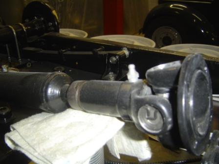
Since my last report I remade the prop shaft with new universal joints. It was a fairly simple job, because after some measuring - with some great help from my friends of Anglo Parts - I discovered that the ones for an MGB are a straightforward fit (www.angloparts.com).
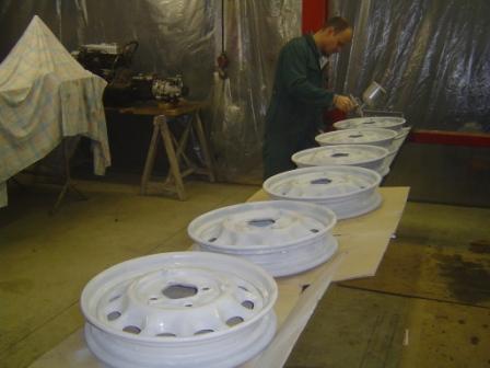
In the meantime my son was taking care of the wheels. They where sandblasted, and then he sprayed several coats of filler in all the rusts damaged places, followed by sanding them down. And again, and again, until all the bad markers are gone
He is very patient J.
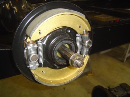
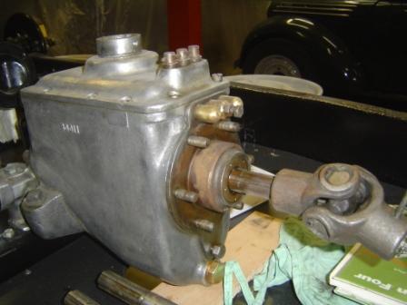
I also did a close inspection of the inside of the gearbox, and it looks in almost perfect condition. So I just replaced the oil seals and one bearing, and I am pretty sure that will be enough. I also rebuild the rear brake adjusters and the pull system, and mounted the relined brake shoes. All necessary things before I could mount the rear brake cable and handbrake system.
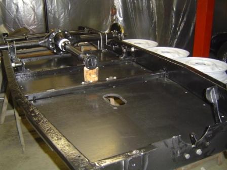
But to find out how the cable system fits in the chassis, I was looking at the pictures I made at Georges workshop earlier this year. So I discovered that I still had to make the floor boards and put them on their spot. The result was that I had to unbolt a lot of what was already in place, because with the gearbox an prop shaft in situ, putting the floorboards in is impossible. Even the rear springs had to be loosened on their front side.
So I bought a good quality 13mm. multiplex plate and made the floor boards, thereby using patterns I first made from cardboard. Then they received several coats of black paint, and we put them in place. In fact a fairly straightforward job, but still good for a whole day off work, not counting the time I will need to replace what I had to remove.
I always try to look far enough ahead to avoid being out of parts to keep the progress going, but in my young enthusiasm J forgot that I also have to look in what order the parts have to join the chassis. Seems all very logical, but when you have a project like this that arrived in cardboard boxes, its always a bit of a jigsaw puzzle.
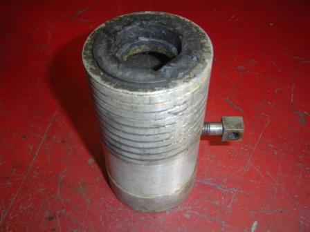
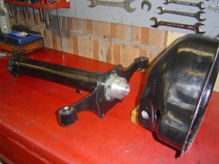
From that angle I looked a bit closer to what had to come, and repairing the clutch sleeve was one of the major things on the progress list. That part is located in a tube, bolted one side on the bell housing, other side on the gearbox. Inside there is a shaft connecting the outgoing movement of the engine to the gearbox, after the clutch. Simply said: engine > clutch > bell housing > between tube with prop shaft > gearbox > outside propeller shaft > differential/rear axle. As you can see, a nice piece of mechanic.
So to move on with mounting the drive line, until the point where the engine has to be bolted on, I have to make sure the whole clutch operating mechanism is ready. The between tube is bolted on the gearbox, and the handbrake mechanism is bolted on the between tube. And since it is a one cable system, I can never complete the rear breaking system without tube and gearbox in place.
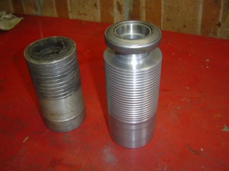
The old clutch sleeve has a completely worn out carbon lining, and I was not able to find a new one. But no problem, by my previous spy work I knew that it could converted to a more modern system, by using a roller clutch bearing. A bit searching learned me that the bearing of an MGB is perfect for the job. So I only have to make a new sleeve, accepting that part J.
 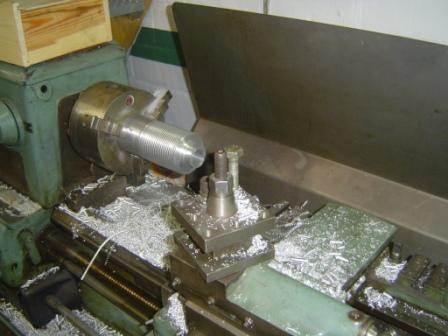
My brother in law provided me with a 85mm. solid aluminium bar, and out of that we made a nice new sleeve on the lathe, with even the grease lines in it. It is made a bit longer than the old one, but that will be corrected after a try out. Because I am not 100% sure where to drill the hole for the pull eye of the clutch mechanism, that have to wait also until I measured everything by bolting it all together, measure it correctly, and then bring it to the right size. One or two extra hours work, but I cannot afford to take a guess, making that sleeve was a too big job. And beside of that, I dont have an extra aluminium bar J.
09-12-2011, 10:11
Geschreven door Jeff OdH 
|


