All is changing very
fast now, once the project goes to the trim shop, you can see it become a car
day by day.
But first I have to
say that I made an agreement with my friend Michel- from the trim shop -that I would come to the shop everyday to
give him a helping hand where that was possible. Not only because he was so
friendly to take my car as an extra he has a waiting list but also because
on certain points there are decisions to be made, based on a little bit of
imagination.
Again because of the
little one can find about these cars... And no, the book Original Morgan
cannot solve that problem, a few photographs are not enough to rebuild a car in
the correct way. And beside of that, sorry to say, but the information you can
find in it is not so correct at all.
But in the past I
made my homework where possible, collecting a much photographs I could find or
take myself, and that should be enough to build a nice interior.
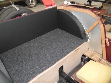
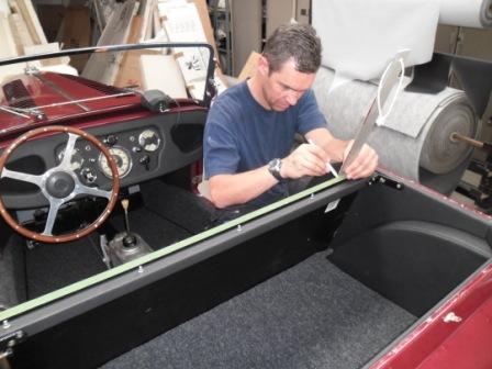
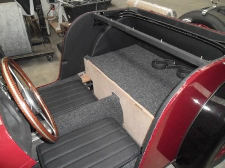
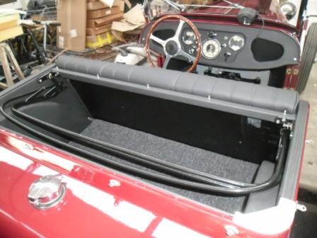
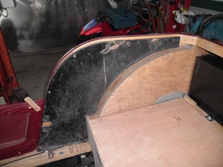
So we started off
with the space after the bench seat, what you can call the boot. First he
made the upholstery for the wheel arches, followed by the mat, and then
followed by the rear and side panels.
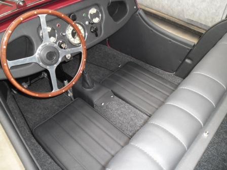
Then we moved to the
cockpit of the car, and we brought the sills in shape with a strong foam, so
we could make a nice curve from top to bottom. Then the kick panels were
made, and the mats for the bottom.
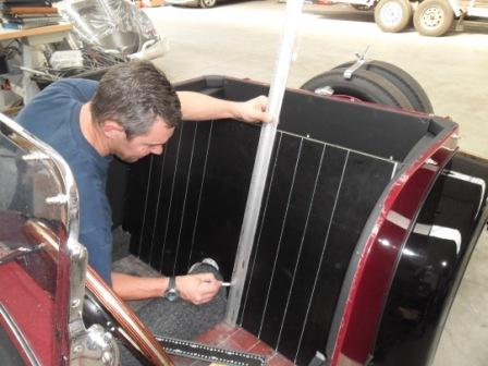
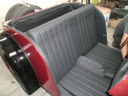
The Michel started on
the back of the seat, carefully measuring out where he had to make thestitches, so it would be visual perfect.
Again we had to use a bit off imagination, but in the end it all came well.
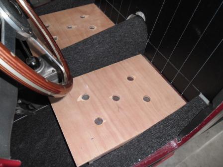
Whilst he was
struggling with that back, measuring and counting, I made the wooden undersides
for the two seat cushions, and a simple system to keep them in place, although
easily removable. We agreed to make the seat cushions 8 cm. high, and in 30
minutes they were ready.
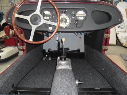
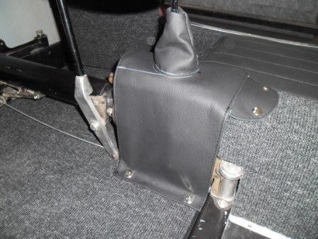
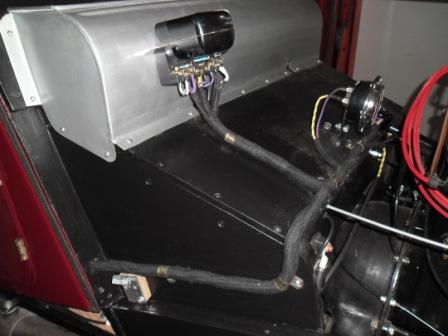
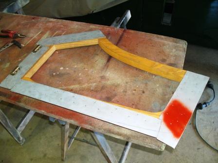
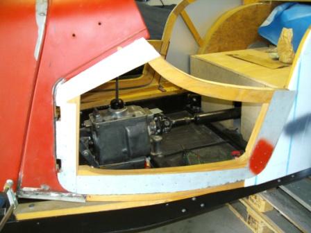
Then a cover for the
gearbox was made, based on a few pictures all of them showing a different
model of cover and our imagination. Correct or not? The result looks fine,
and thats ok for me.
Then the bench was
ready, and the puzzle felt together. For me the result is very nice, and people
that have seen it agree with that. I think we made a great result, started with
what we had to compare with.
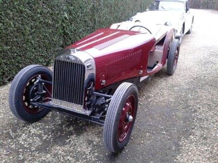
Now it is just a
matter of getting the front wings in place, and put the aluminium/ rubber profiles
on them. I am happy!
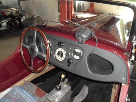
Now the body is painted, I can go on with the dashboard, the electric components and cables, in fact with a lot of things that are needed to make the car run.
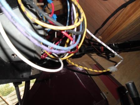
So I started putting the wiring loom in the car, because that have to be done before the dashboard comes in, so you can connect all the wires without laying on your back underneath the dash.
It was supposed to be a straightforward job, because it is a new wiring especially made for me by Autosparks (http://www.autosparks.co.uk/) But it turned out that the main wiring cable that goes from the regulator box to the dashboard was too short. I could solve that problem by giving the cable another route, but I dont like that. On the pictures of my old worn body, I could perfectly see where it has to be. So no concessions, it has to be right.
First I contacted Autosparks about it, and they were surprised but very friendly and helpful. They never had that problem before I was told, and I am
willing to believe that. With only a few LHD examples of this specific model made
or left, I simply think they never had to make a LHD wiring before J. They suggested
that I measured everything up, send the wiring back, and they would adjust it
where needed. But my proposal was that they send me 1 meter of every wire and
colour they used, so I could do it a la carte here at home, and so we did. In
3 days I had the wires, and it took me half a day soldering and isolate the
wires separately, followed by a complete isolation coat of cloth tape. You
cannot see where it has been lengthened, and it fits like it has to be, so that
was what I wanted. There colour codes where absolutely perfect, so from that
moment on, it was a real straightforward job J.
After that I had to make extra wiring for the indicators, because the
car did not had them in his younger days. Not only a wiring for the switch, and
the control light, but also wires to the front and to the back of the car. Not
too difficult all that, but it took a lot of time to fix all the wires in a
proper way...
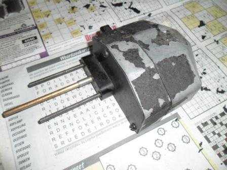
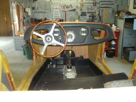
Then the renovated dashboard came in, and I did a test start to see if
all my electric components where working. Apparently the dynamo was not
charging, although I tested it after the rebuild. So I looked and tested
further, and the control box was the bad guy. This control box has 9
connections, so an example from an MG or so could not be used. But it came out
that it was no problem at all, I simply bought a new one at Auto electrics. (http://www.autoelectricsupplies.co.uk/)
So now I could start putting the windscreen together, and placed on the
car. A while ago I had the windscreen frame dissembled and the chroming company
had made it look like new. They also took care of the pillars that come on
the body, and where the frame fits in. Those pillars where brand new ones, that
I bought from George, the series one pope. He had a few of them made by casting
company especially for him, made with some old scrap as an example. They still
where in ruff bronze, but the chroming company took all the finishing work for
them, and the result is great.
The glass part of windscreen was also in bad shape, scratched all over.
Buying a new one was impossible, it did not exist. And due the special cut out
parts for the wiper mechanism, the screen of a younger model was also no
option.
So I took my old screen to the local glazier, to ask him if he had a
solution for me... He looked at it and said, OK, I cut you a new one. He did it
the following day, and then it went to a specialised firm to be hardened, so it
can be used as a car windscreen. Simple as that, where was I so worried about J.
The new glass part went in the frame and I sealed it with Sicaflex, a
windscreen sealing product used to glue windscreens on to cars. First I
measured the glass, and then the inside of the windscreen frame. Then I made
some rubbers and placed them in the frame, so the glass was already fixed in
place. Then the Sicaflex was injected and nicely wiped off where the glass
meets the frame. A job where one should were gloves, as I know now J. But the end
result is perfect, and my hands became clean again after a day or 10 J.
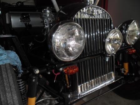
A new rubber seal (MG TD) on the underside of the frame - where the
frame meets the body came on, and my renovated windscreen was ready to be put
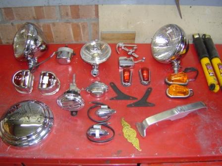
on the car. Then the headlamps and front indicators came on, and from that
moment one it started to look like a real car.
Then came the wiper motor in sight - or rather not - because it was not
in the pile of parts that came with the car. It has to be a Lucas as used in
so many British cars of the past. So I bought me a used example on Ebay, that
had to be reconditioned. You find them also all ready, but the price is than
rather high.
The one I bought looked rather tatty, but inside it was not bad at all.
After cleaning the anchor and windings I putted new brushes in, and a test
proved its working. Then I took all the paint off and gave it 3 good layers of
wrinkle paint, so now it looks like new. A new wiper mechanism and wipers were
ordered at Vintage car parts, so everything was there to finish that part. (http://www.vintagecarparts.co.uk/)
Great sight, and a real boost to go one with the rest of the
restoration. I did a security check of all the bolts and nuts that secure the
suspension. So I could say to myself: OK this is all done and would not fall of
when we do a test-drive J.
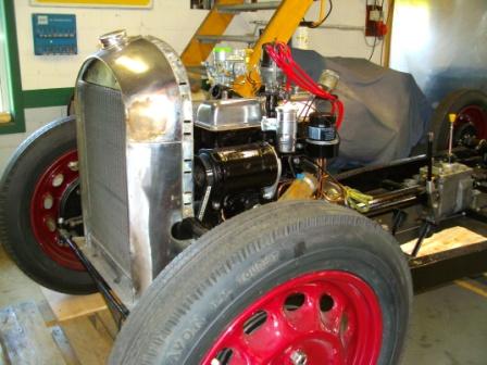
And that moment came very fast, it was itching too much, I had to do a
test drive. Simply on the little road here on the back of our garden. I did
this first run together with my granddaughter, my strictest judge. We were
sitting on improvised seats, in fact wine crates with a little foam on top, and
a simple wooden plate was promoted to backrest. It was a short but great ride
without any comfort, no doors, no wings, no licence plates... But oh boy, was
this FUN ! And... the car was running surprisingly well.
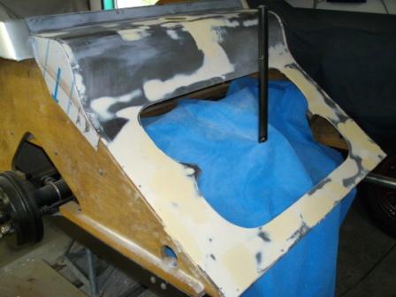
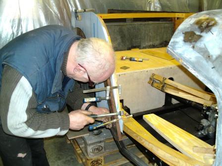
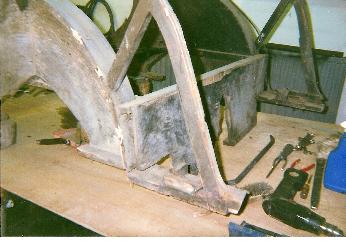
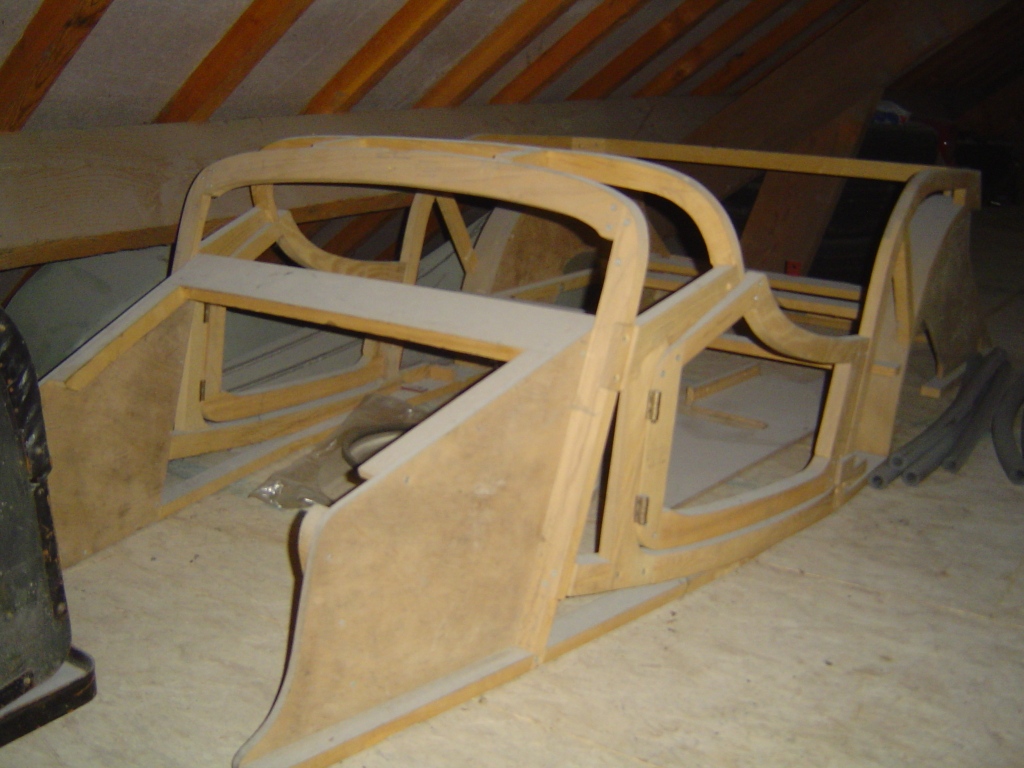
Next step: preparing the car for the upholstery company. A bit painful
for me, because I like to do as much as possible myself, but for this I needed
a specialist.
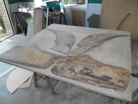
The problem was that I had only the sad looking panels from the old
interior. No seats, no backrest it is a bench type nothing. So everything
has to be made using the pictures a took, every time I had the chance to see a
series 1, and what I could see in the Original Morgan book etc.
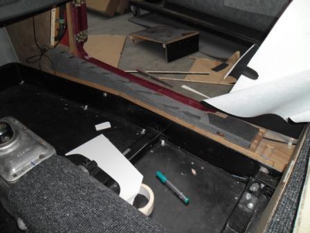
Luckily I also had the side panels from the boot, and the wooden piece
that crosses from left to right and acts as a support for the backrest, and
also fixes the hood frame. So I could exactly determine where that back had to
come, and that seems to be good start...
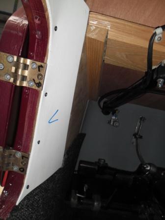
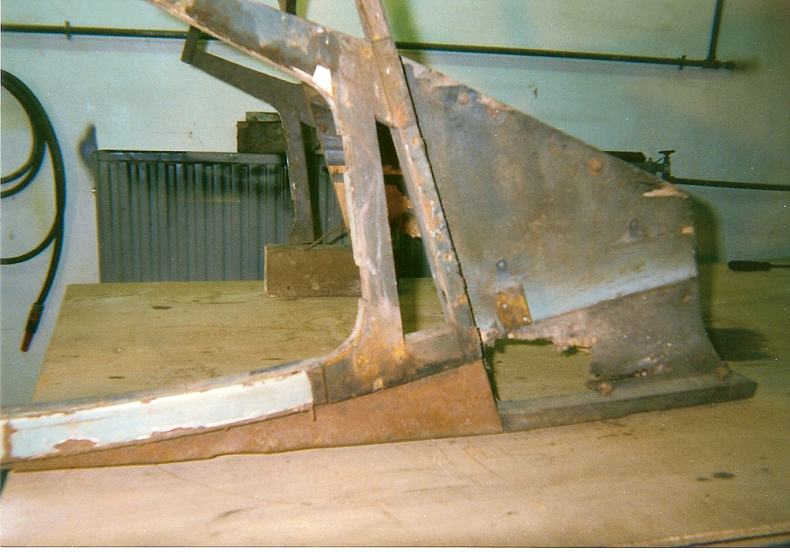
So with a little bit of fantasy and a part of common sense, I was able
to make a backrest that seems to be of the right dimension, and sitting in the
proper spot. Not easy because I had no references, but it all seems to be in
the right place.
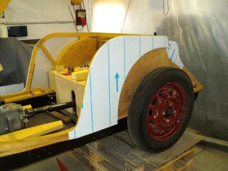
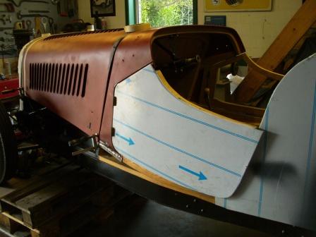
Then I made new side panels, so the upholstery man can work on a good
base for Those Items. I find that it is not his problem that my car is missing
some parts, I have to provide the basics and information he needs, so he can
make an upholstery as I like it to be.
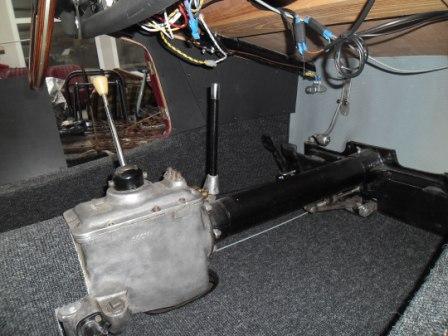
Then I made the little benches that come under the seat cushions - high enough
so that after cutting them down a few times, they were adjusted to my
personal length. An important matter, the space inside is so limited, that
every cm. counts. And beside that: I dont want my head to come out above the
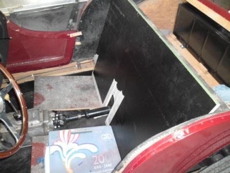
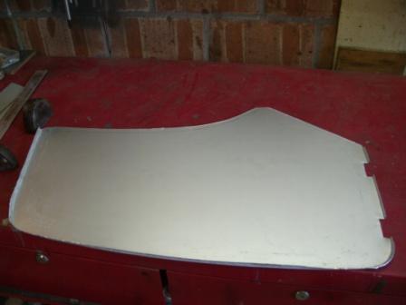
windscreen, my hair is already getting so thin J. And finally I made the tunnel for the prop
shaft, another missing part. And again I had to use my imagination to create something
that looks as I think it has to be. In
one movement I also adjusted the height of the tunnel to what will be the total
height of the seats, so it will all look as if its made for each other J.
So up to the trim shop now, a very big and final step in the restoration
process of my series one...
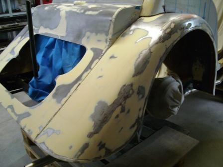
Now the ruff work on the body is done afterwards its seems that it was
the easy part - it is time to make everything tight, smooth, and ready for
painting. But all that is faster said than done. Mainly it means hammering as
much as possible dents out of the body, filling some dents with thin, and using
a metal file (more a grater) to straighten the metal. All that to ensure that the
use of filler can be limited to the minimum.
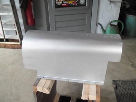
But some dents in the bonnet and the rear panel do not differ, the
condition of those panels was terrible after about 40 year storage combined
with a few house moves. On top of that the
(after war) metal is so thin (0.8 mm.) that you have to be careful when you
start sneezing J,
the metal was stretched where dents used to be, and it was impossible to get a
plain surface just by cold hammering.
So I had to use a technique I learned some 40 years ago as helper of an
old coachbuilder - real craftsman - or at least what I still could remember of
it. Shrinking they call it, and its all in that word. I had to shrink the
metal by making a little round spot (about the size of a 2 piece) flaming red
with the blowtorch, and then fast round hammering from outside to the inside, then
followed by cooling the whole thing with a bit of water and a sponge. To be
honest, it took me some time before it would go a little bit like I hoped, but after
some training spots on a loose piece of metal it did. I think I spend about 5
hours warming, hammering, cooling and grating. But after that it all looked
straight enough to take the next step.
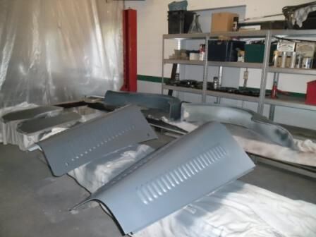
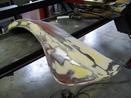
So now I made the surfaces (except the front wings) straight with a good
quality filler, sanding them down, filled the little dents again, and sanded
them down. And again, and again... At a moment it looked as if the whole body
was covered with a thick layer of filler, but thats only a first impression. I
think that even on the worst parts, the filler has no more thickness than 2
millimetre. I used 3 kg. of filler on the whole body, and you can count that
75% comes off again with the sanding. For me that result is more than
acceptable.
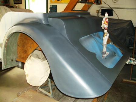
After that came a coat of spraying filler, to get the last scratches of
the ruff sanding out, followed by a few good layers of primer.
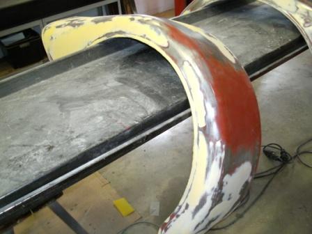
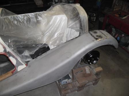
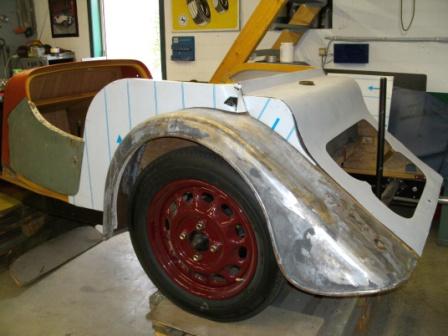
The front wings came next. There metal is much thicker, so I had them
sandblasted by someone that knows how to handle such parts. A lot of filler and
old paint came off, but basically they where surprising good. I just had to
weld in a little piece of metal where they fix on the front support, because
that part is double, and so rust can go its way there. And on the rear where
they are bolt on the rear wings, that also needed a little bit off new metal.
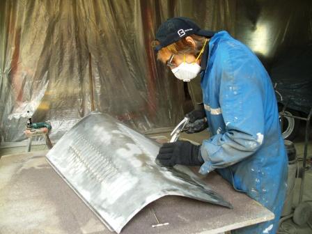
But making them straight was another story, it took a lot of time,
simply because they are so long and in the past on several spots repaired with
a lot of filler.
Getting a nice smooth surface was not so easy. Hammering the dents out
was one thing, getting the wings straight after the filler another. Especially
because I first tried to do it with the sanding machine, but I could not receive
the result I wanted.
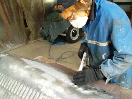
To cover a much greater part of the wing in one time, I made a simple sanding
block (60 cm) from a piece of wood, and nailed the sanding paper on the head
ends. So now I could cover much longer strokes, almost the whole wing, in one long
smooth move. That worked well, so again filler sanding filler sanding and
so on. Than after much elbow grease, spraying filler came on, sanding again...
and then followed by a few layers off primer.
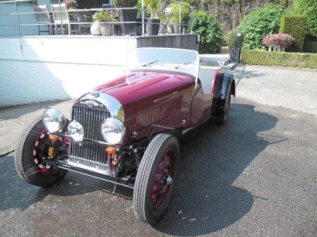
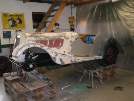
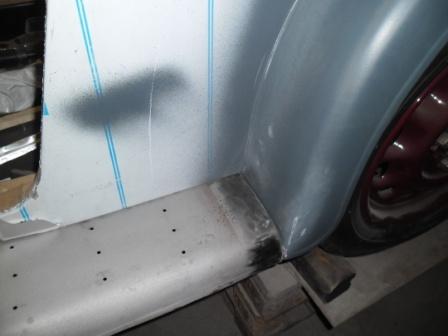
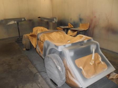
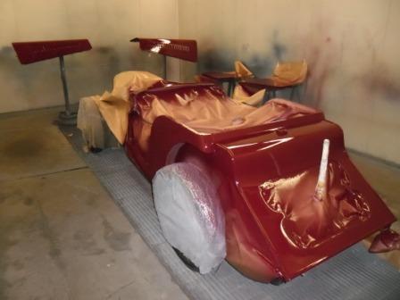
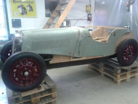
From the start of this adventure I decided that the body would come in a
warm maroon, and the wings in distinguished black. So now it was time to paint
the body, so I could finally go further with the more visual part of the
rebuild. For that purpose I hired the spray cabin of a small garage here in the
village, to do the paintjob myself. Geert the young owner dont mind to let
me work in it, because I used to work in several paint shops when I was a lot younger.
One of them was in fact in that same garage, but then owned by his father, who
is after 40 years still a friend. So over the years I always managed to
maintain a part of that skill, as a helping hand here and there.
I used two pack paint off course, but not the version with a varnish end
coat , because that finish would be to modern. But on the other hand, to make
the end coat stronger, I always use a bit of pure two pack varnish in my final
coat of paint. The result is always stunning...
After
solving my problems with the steering box, I had to go on with the project, it
has been neglected too long. So here is an update, but I am already a bit
further in restoration than in writing, isnt that good news?
After placing the old panels on the skeleton body, just to have an idea
how the car looks or have to look, I had to decide how to remove the old paint
without damaging the body parts.
To be safe, I decided to have the paint from most of the parts chemically
removed, simply because the metal is only 0.8mm thick. When you try to remove
the old paint purely by sandblasting on such a thin metal, the chance that you
end up with nothing than scrap metal is around 100%.
And yes, I know there are several meanings about chemical paint removing
on car parts, the product stays between double plating an things is a common
complain, but I felt I had no choice. So I took everything off and brought it
to ICS in Sint Niklaas. They have a fairly good reputation in chemical paint
removing, so I decided to let them do the job. The factory didntlooked inviting, but the work I saw did. So
come on, and go for it....
I had to wait a few weeks before my parts were ready, and the result is not
all nice to see, but exactly what I expected. All the old paint was gone, and
the rusty areas completely visible, exactly as I hoped.
So now it is time to do some cautious sandblasting, on the rusted parts.
Theo my best friend offered to do it for me, I just had to set him on track,
and help a little bit with the difficult parts. We did the job simply at home, with
the little DIY sandblasting tool, and no more air pressure than necessary. That immense job took a few days, mostly
because the air compressor could not follow the huge demand on air. Theo had to
wait regularly, but at the end I had all the thin parts (that is except the
front wings, that are much thicker and can be done by a professional
sandblasting company) rust free and put in a protective red paint. Some kind of
a friend, no?
I repaired the cracks in the rear wings, reinforced them, hammered the
dents out, and welded new metal in the holes from the incorrect rear lights. No
holes anymore at this stage, I make the new ones at the end with the new rear
lights as a pattern. After the wings I did the same with the rear panel, the
back where the spare wheel comes through. A hell of a job, again because the
metal is so thin, and because the panel has been repaired several times in the
past, and not always by the best body repairer... But as my father used to say:
difficult works also, a bit slower, but it makes you smarter J. Then I
placed the rear panel and the rear wings on their place, and attacked the left
over dents with metal putty. Then a tour with abrasive paper, and again putty,
and so on and on...
Until the moment I decided that the result was good, and I could paint
the rear of the car in primer. Not only a great sight, but a real boost to
continue working.
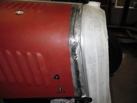
With the rear quarter panels I had some other plans. They were so bad on
the lower part, that I definitely had to make new ones. So I thought, I better
make them in aluminium. And so I bought a plate off aluminium that the
professional aluminium van builders use. It is called in Dutch anodised
aluminium andhas a far better quality
for this kind of use than a normal plate you can buy in the DIY shop.
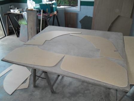
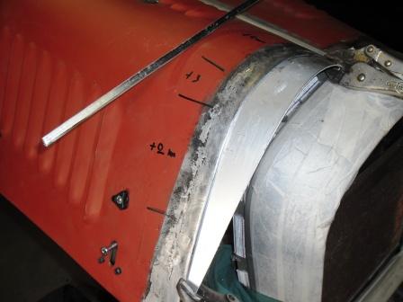
Making the quarter panels was easier than I expected. But to be honest,
I have to thank another friend Kris on that, for his good advice and help. He
has some experience with that kind of a job, from the time he restored his
Hotchkiss. So first we made some patterns from cardboard, and then we cut out
the aluminium with an extra 2 cm on the edges. Than we placed the panel on the
skeleton, and use spanners and some plywood to keep it strongly in place.
Hammering the edges around the wooden frame was easy, and then we fixed it with
nails. Piece of cake...
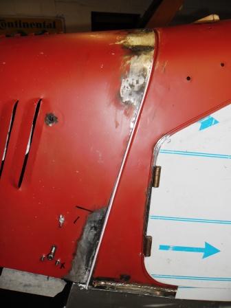
The doors where not that easy, but at the end also not really difficult,
because the main system stays the same. First you have to fix metal plates on
the wooden frame, creating the door shape. And that is the base where you fold
the aluminium around, so making a door skin. First we made the metal plates,
and fixed them to the wood with nails. Then with the old door skin as a
pattern, we cut the new metal plates in the correct shape, and did a try out on
the car. After a bit extra modelling, we placed the door frame on the
aluminium, and used then that as a pattern (+ 2 cm) to cut out the definitive door
skin.
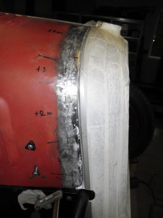
The plate came then on the naked door frame, fixed in place with
spanners and plywood, and was hammered around the metal plates, creating a
double edge. On the top side the plate was plied direct on the wooden frame and
fixed with nails. And thats it!!!
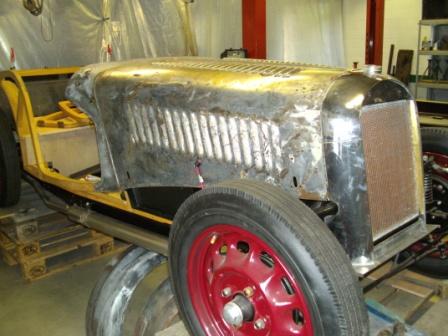
And now I am fighting a real war with the bonnet. She(according to the
problems I came on it must be female) was in a very bad state, and the shape
was if like a truck run over it... twice J. The front side was corroded and sharp as a
knife, so I had to make a new front strip for it, 5 cm wide. Then plied that
over on one side, so creating a double edge. That is not only very strong, but
also can be plied in correct bonnet shape. After a visual test to see if it
would follow the line of the radiator, we cut off a ± 4,5 cm strip from the
bonnet front, and welded the new front side on with the TIG. Until that stage I
hoped no I was sure - that the front
of the bonnet would nicely follow the shape of the radiator. But that would
have been too good to be true. Although the result was already nice, it was
clear that Santa Claus does not come for grown ups with bonnet dreams J. But still I
was happy with the result, it was not bad at all.
To have the shape correct - we speak about a few millimetres only on
some places - I am now preparing everything to adjust the shape of the bonnet
to that from the radiator. That has to be with lead, it has to be strong. Not a
real easy job, but one that I did before and with success. So I am convinced
that I can reach the result that I like.
A first and very important stage is the preparation of the metal, it
must be 100% clean to give a correct grip to the lead. Than bringing on a thin
coat of fluid lead on it with a brush, warm that up with a small (gas)flame,
and when it gets flow able clean it up a little with a clean rag. A tinned
surface must be the result.
Than taking a rod of lead, warm it up next to the prepared surface, and
melting it on in little dots. After that I warm it again a bit, and push the
lead in the (almost) right shape with a wooden spoon. After that, the body
file, elbow grease and a good eye, must do the rest.
It has been far too long since I posted
a follow up on my project, it looks like the older I get, the scarcer the time...
But anyway, here is an update on the steering, an item that caused a lot of bad
sleep, again because the difficulty of getting parts. Worries that afterwards a
based on nothing...
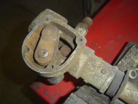
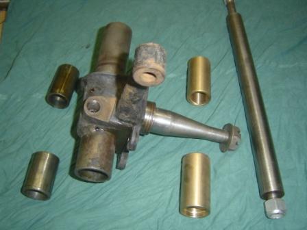
The steering box that
came with the car was just an worn out, rusted and bended box and tube, even
the cover was missing. Nothing that could be used again without a proper parts
supply.
So I started looking
for second hand Buhrmann box of the same type, but that was as searching for a
needle in a hay stack. The biggest problem was that I needed an left hand drive
steering box, a right hand drive would be a bit easier. So again I had to ring
George the series 1 pope, and he gave me the advise to go looking for a Bishops
box as used from 1951 to ± 1976. The column would be about 10 cm. too long, but
making things shorter is easier than making them longer J. He advised me also to look for an
chassis clamp, because the fixing to the chassis is completely different.
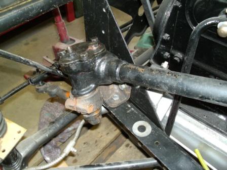
Left hand drive, so I
thought USA. And the first company that crossed my search on the internet was
Morgan Motors of New England, in Copake NY. I mailed them, and the next day I
had a mail back from Linda Eckler, that they had a second hand example for me,
completely overhauled and with chassis clamp. About two weeks later it arrived
with UPS, and I could start with the adjustments.
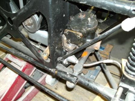
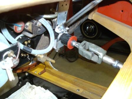
Because of the
positioning of the clamp the steering column comes a bit further outwards, and
that makes that it comes under a slight angle regarding to the dashboard. With
other words, the steering wheel would not be in the same line as the dashboard,
but a little oblique.
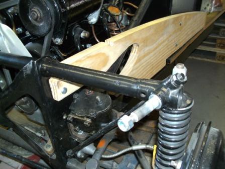
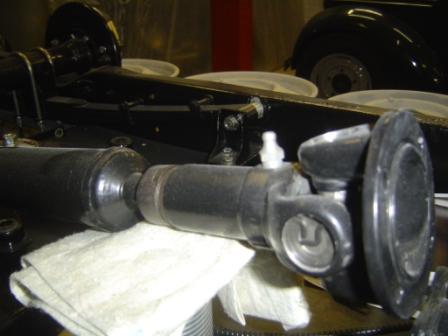
But since I had to
shortened the whole column, I could easily solve that problem by using a little
universal joint in the last part, hidden under the dashboard. My neighbour had
an written off Renault in his backyard, and that was the donor for the
universal joint. I shortened the tube, took out the rigid steering axle, and
shortened that too, but on the latte. The diameter was adjusted to that from
the universal joint, and everything could be back together. On the other end of
the universal joint came a short piece of the axle, and that fits in the boss
for the steering wheel. Problem solved!
Next things to do is
the body, I am looking forward to it! In
fact I am busy on it at the moment, so an update comes very soon.
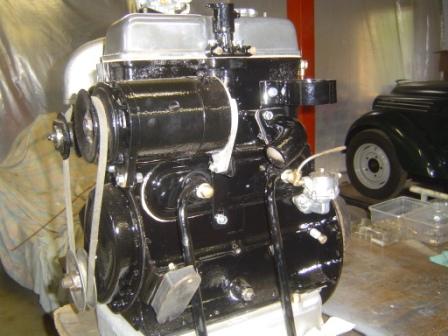
After the successful first start of the engine, I was rather pleased with
the results of the work I did until now. Hearing the sound of engine for the
first time is always a milestone in a restoration project. And since I started
from a pile of parts in a box, this was more than a milestone for me.
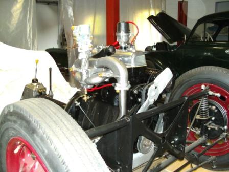
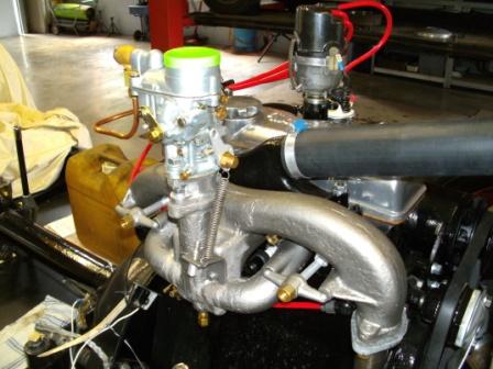
After that I mounted the exhaust system, a rather straightforward job. I
just had to reshape the pipe that comes to the exhaust collector, because that
pipe runs through the chassis. It has to be in the centre of the hole thats in
the chassis, to avoid that it would rattle against it. No problem, a bit of elbow
grease and the heat of the welding flame did the trick.
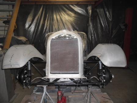
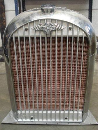
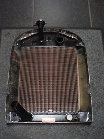
Until now I always walked around it, but now the next thing to do is the
radiator. Not only to go further with the engine, but also because I need the
radiator shell to outline the body parts. But as I mentioned before I had a big
problem regarding the costs of a new radiator, and so I had to find a cheaper
way to fix it. To have it re-chromed it has to be an empty radiator shell, so I
have to find someone that can make me a radiator that fits inside the original
shell, it is the only solution.
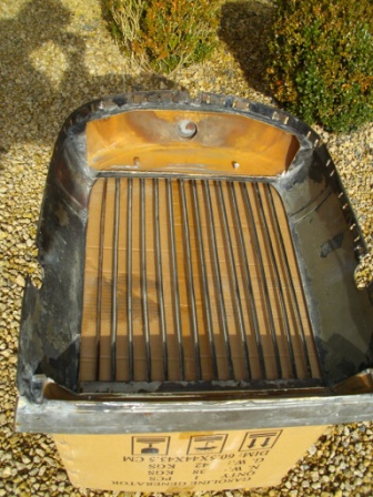
To find someone that can make me what I have in mind, I cut out the old radiator
core, to find out how much space I have inside the shell. Then I made an
technical drawing of the new radiator to my idea, and presented that to about 5
radiator specialists.
I had several reactions from the type yes we can do that, and one that
came with al lot of good suggestions about it, straight from the first contact.
I realised; this is the man I need. He is not only thinking in the same
direction as I do, but thinks even more forward with a lot more knowledge. And
that he was the cheapest of them all, was another great advantage too J.
After an extra telephone call I brought my radiator to his shop in
Oudenaarde, and there he bombed me with facts and tips about how he would build
it, as was it his owne. We agreed that he could do it in spare moments, because
a few weeks extra was no problem for me, and that he would keep me posted about
his progression. So I left my precious part in his good hands and left,
convinced that I have found the right guy.
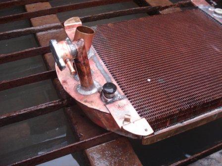
After a few days I already received the first photographs of the naked
radiator core he was going to use, and that mail traffic would go on for a few
weeks, until the radiator was finished. He made some good changes on my
original plan, but always after discussing that first with me. The finished
product is perfect, and I had it in a 4 weeks. Thanks Koenraad Wynants, you are
a great guy and a true professional with hart for your job.
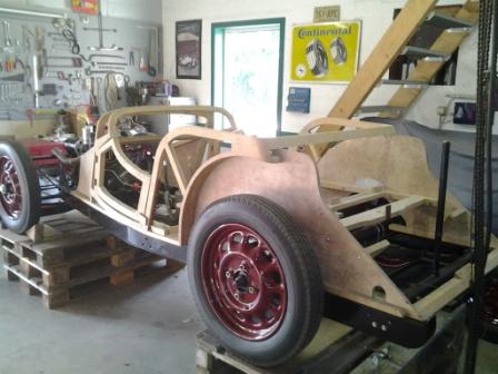
Then I found it was time to restart my restoration, it has been
neglected again too long. My first good intention for 2013 is: to work on it a
half day at least every week. I hope I will keep it J.
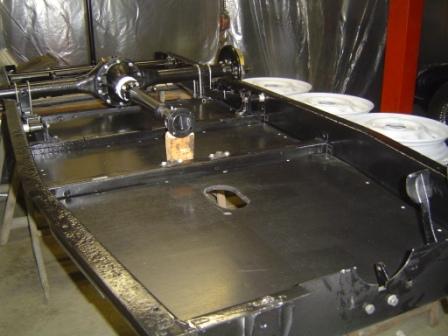
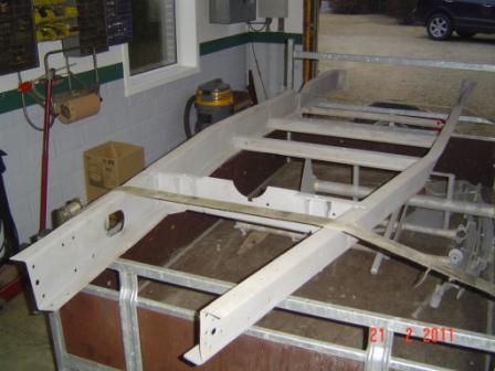
As a start I took the skeleton body from the loft an gave it an extra
layer of a wood preserving product, so the bad bugs would not eat it J. It looked
very nice afterwards, in fact it is a shame that you cannot see it once the car
is finished.
Then I measured it out on the chassis, and in the length it all looks
correct. Then I just had to line it out following the inside chassis shape, also
a piece of cake. So time to lift it a little bit, put some sealing-like product
between body and chassis, and put it on his final place. Then I drilled the
holes for the fixing bolts, and bolted the woodwork on the chassis. Again a
nice sight!
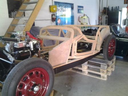
To satisfy my curiosity I took the old body panels from the loft, to
measure them on my car. It all seemed to fit in a normal way, until I
measured the distance between radiator shell and scuttle.
Great consternation, it seems to be 6 cm to long. The bonnet could
simply fall between the scuttle and radiator, an error on the skeleton? A bad
night followed...
But then I discovered that the radiator dont have to stand perfectly in
the upright position, as I placed it. In fact it is slightly tilted to the
bulkhead. So I moved it, and the second measurement from bonnet to scuttle gave
a complete different result. The distance was almost right now, and perfect as
a start position. So again I put the bonnet on. And now it fills nicely the
distance, and it follows perfectly the shape of the radiator shell. A heavy stone
fell off my shoulders...
Now I am looking for a safe way to remove the old paint from my original
body parts. Sandblasting is not an option, because of the deform that appears
on thin not strengthened parts. So I made contact with a firm that does paint
and rust removal with a chemical process. They are sure that there process fits
my requirements, and the parts are going there next week.
It has been a long time since I posted some material about the rebuild
of my Morgan. But as I found out last year, the summer months are not the best
to obtain some progress. There are so many other things requiring my attention,
that I neglect my baby. Shame on me!
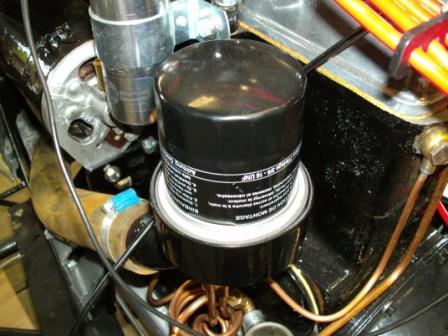
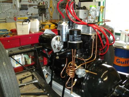
Nevertheless, I made some progress since my last report. I can say that
I finished the engine, but to do so I had to make some parts myself, thereby
the spin on oil filter conversion being the most challenging.
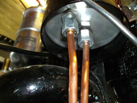
I spend a few hours at MANO, a firm that provides all kind of parts and
tools for the industry. Luckily we managed to find the right adaptors and tubes
that I needed to make the conversion plate. After that the plate itself was a
simple job on the latte, making it on a logical thickness and drilling the
holes on the right spots. The right tread was simply tapped by hand, and it was
done.
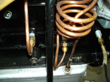
Then I had to make some conversion adapters on the oil lines going from
the side of the engine block to the oil filter and back to the oil pan. All
those original adapters are in BSF, and if there is one thing you cannot find
in Belgium... right. So I welded some current adapters to my old ones, one side
taking the new oil pipes, the other (old stuff) going in to the engine. Rather
simple, and safe.
The dog drive for the distributor appeared as a problem, but in fact was
a piece of cake. I first made a tube of the correct length and thickness, and
then made on both sides the necessary cut-outs. It fits perfectly, does what it
has to do (turning), and so I dont expect future problems with that.
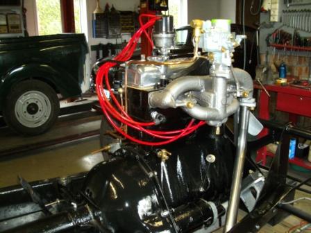
So with the distributor now in place, it was time to set the timing. I
just turned the nr 1 cylinder on his compression point, marked out where the
rotor arm was pointing to, and took that as a standard to start the festivities
with... Then came the spark plugs in,
and could I make the high tension cables.
But then it stopped, no time anymore. The Morgan has gone in his summer
sleep J
But on a very sunny Sunday - 12 august 2012 I decided that it was time
to wake the sleeping beauty. So I first made a temporarily oil line to an old
oil pressure meter. I thought that at least would be something to keep an eye
on, as it would start. The I placed a fresh battery on the floor board, made a
decent plus and min connection, a temporally fuel line, and a current line to
the coil. Off course I filled up the engine with oil (half synthetic), and
bolted the exhaust on.
OK this was the moment of truth... With the plugs out I let the engine
go round on the starter, to build up some oil pressure. That turning around also
provided fuel to the carburettor, so we were ready. Plugs back in, power to the
coil, and then I pulled the starter.
YES ! after a few seconds the engine came alive, after ± 40 years! A great
moment, and what a sound J
This test was still without radiator, because I still have to remake
that part. It has a slight leak and it has to be recromed. So without that necessary
cooling, I only let it run for a minute or so. But the radiator was on in about
15 minutes, still leaking (not really bad) but better than nothing J. So I restarted and let it run for 10 12 lovely
minutes, without any problem. A great day, a big step forward for me.
So next BIG problem is my radiator. I had a price quote from a
specialist in the UK, I think he is the only one that can make a series I
radiator. It comes out on about 5.000, but to be honest I cannot spend that
amount on a radiator alone. What he makes is top work, I have seen it and believe
it cost that much to make such a radiator. But no, my restoration budget cannot
cover that. So if anyone can give good advice on my radiator, PLEASE DO !!!
With the chassis nearly completed, except some minor J things like an
incomplete steering box and no front shock absorbers, I can start thinking
about putting the engine together. I
dont expect it to be an easy task, because of the lack of
documentation, but mostly because I did not took it apart myself
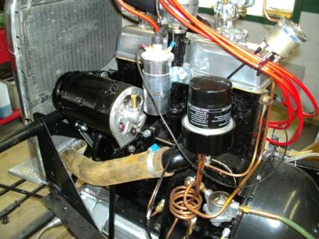
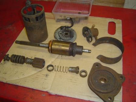
I thought it would be a good idea to start with some parts that come
aside, but are necessary in the whole picture. The starter and the dynamo
needed some good attention, as did the petrol pump. They all looked if as they
have been lying in a barn for more than a quart of a century, and in fact they
did
So I started with the dynamo, took it carefully apart, cleaned
everything and checked the state of the different parts. The brushes where
perfect, and the anchor was made as new on the lathe. To be sure it can go on
for another 25 years, I also made a new bronze end bush. I will be 85 by then,
so that must be sufficient J. Then
I put the whole thing back together, and tested it simply by giving it power so
it had to act as an electric engine. Result: 100%.
Than the starter, same procedure, same state. Just the starter relay,
in fact a cable operated mechanical part that makes the connection between the
main power cable and the starter. That needed a lot of internal cleaning, because
dirt and corrosion has took over from clean copper connections. But there is
nothing that a good wire brush cant clean, especially if it is mounted on a
drill. The test was also 100%, and I was happy J. The petrol pump also just needed a good
cleaning in and out, a test, and OK. This must have been the easy part, it was
going to well.
Then came the serious work The drive line of the engine was already
done by the previous owner Jean. But to be sure what was undertaken, I phoned
him. No worries he assured me, the block had a rebore by a professional . They
fitted new pistons, the crank was regrinded, and they added all new bearing
shells. So now it was my turn.
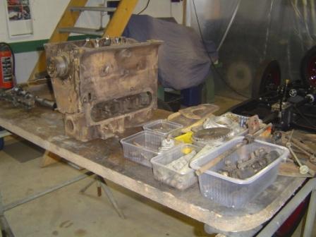
Before starting to put things together, I cleaned the whole inside of
the block, and gave the oil canals a good flush with pressed air. Than I cleaned
the whole pile of parts that came out of the boxes, and laid them all out on display,
just to see what Ive got and what probably comes where. It looks pretty
complete
The two aluminium blocks that have to close the underside of the engine,
once the crank is in, had damaged tread where the bolts of the oil pan have to
come. I decided to go for the easy solution, Helicoil. So I put an oversize
coil in it with inside tread of M8, very similar on the original BSF ¼ tread.
Easy and a perfect, with an even stronger tread than the original one in the
aluminium. I bought four new M8 bolts with the same length as the BSF ones, and
ready!
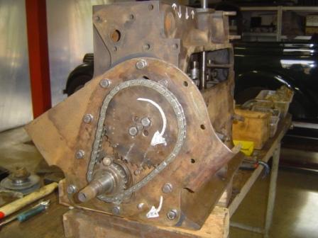
Then came the camshaft in the block, and I put the gallery with the cam
followers in, just to have a better sight on the future valve movement
according to the crankshaft and piston movements. The two sprockets came on
their correct lined spot, and then while turning the camshaft by hand as a
test, I had a what is this moment
The number 1 and 4 pistons where on TDC, and by turning the camshaft
further after the compression stroke on nr. 1, the outlet valve normally
opens. Here the inlet did, so the whole process of filling compression work
and exhaust has just begun. I tried and
looked, and tried and looked, and came to the conclusion that the piston on the
flywheel side is in fact the nr 1 piston, usually that is the nr. 4 And by
looking at the turning direction of the starter,I saw that the engine runs clockwise, looked
at it from the front. Now everything was clean as a whistle, but it took me
some time to find out.
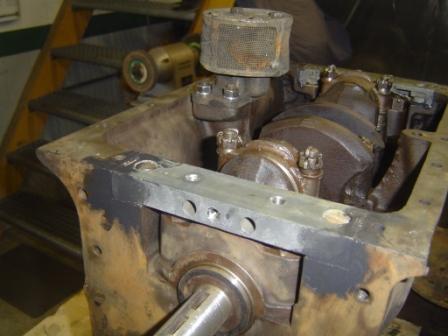
So the front plate came on, and the camshaft and sprockets came definitely
on their spot, provided with and a brand new timing chain and tensioner. On the
back the rear aluminium crankshaft housing was put in place, and carefully
measured out to be perfect in the centre. Very important, because otherwise the
oil thrower cannot work as it should. And, you have a high risk on damaging the
aluminium housing with real bad oil leaks as a result.
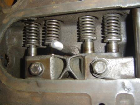
Than the battle with the springs that come on the underside of the valve
pushrods began. It is a strange construction with springs on the underside of
the pushrods, where they adapt to the cam followers. I never seen that system before,
and honestly I dont see the purpose of it. But it is British, isnt it J.
So I tried to put the blocking scales in - they have to keep the springs
on tension - but needed a few more extra
small hands, and a lot of extra space to do so. I even made some sort of a
tool, but nothing helped. So the gallery with the cam followers came back out
to provide the extra space. And then with the help of my son we put the springs
in, put the scales on their spot, and pushed the whole thing completely to the
upper side of the block.
Then we blocked the pushrods on the top side with some locking pliers,
keeping everythingat maximum pressure
and out of the way to refit the gallery. Simple and straightforward, but you
need to figure it out. Than the drive shaft for the distributor came in place,
pointing at the nr. 1 piston, and completely below assuring the drive for the
oil pump. Then I noticed that the distributor is not the original one, it fits
in the housing, but has a completely different fitting to the drive shaft.
Hopefully I can make a conversion dog drive, well see about that later...
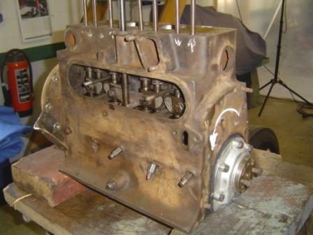
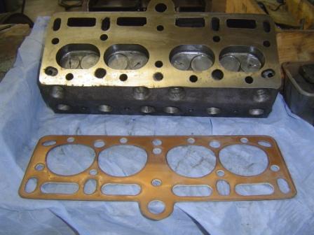
Then the repaired cylinder head went up, using a new custom made head
gasket. It was tightened at 40 lbs, and following the tightening sequence I
found on the website of the Morgan club of Australia.
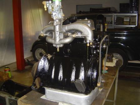
Then I painted the engine , and George told me it has to be in black, so
I did. By now I hope that he meant the colour... JJJ. Afterwards
I added the oil pan, and started to bolt on all the side parts on the engine.
Surely it looks nice, lets hope it will turn even better
So now I just had to figure out how the front dynamo bracket comes on
the block, and make one for the rear side of the dynamo (a missing part).
Then the oil filter will be a real challenge, because the original AC
ZR1 bypass filter is no longer available. So I have to make a conversion plate
to adapt an modern screw on type of filter, and then I have to make and couple
all the oil lines. I found a brand-new carburettor, but the two bolts to fit it
on the collector are not exact in the same spot as the old one. Again some
conversion has to be made, as for the distributor, that is also not the
original one. But it fits perfect in the housing, and has the correct
mechanical advance. So here I only need a custom made dog drive, and that
cannot be so hard to make.
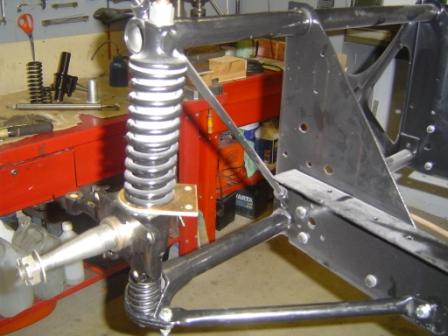
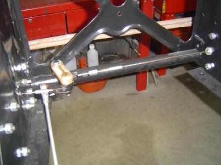
Since my last report I tried to work a bit more on the Morgan, because I promised myself a rolling chassis by the end of the year. And although in first things did not seem to work out as I hoped, the pieces of the puzzle are starting to fall together.
A big thing to do was the front suspension, the famous sliding pillar system. Although that looks a bit difficult or strange , it is not a real problem. I already had new bushes and new kingpins, so cleaning and painting the old units was almost the biggest job. Then I pressed the old bushes out and pressed the new ones in. Then made them a perfect fit with the reamer, and it was done. Putting things back together with the sub frame was fairly simple, with a piece of threaded rod to clamp the whole thing together as my partner in crime.
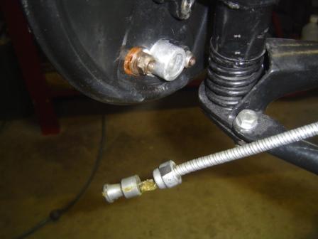
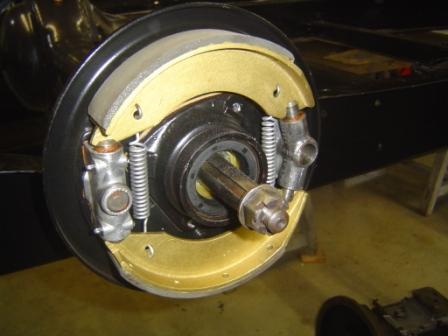
But the front brakes where another story. Normally that hat to be a simple and straightforward job, since I had everything on the shelf.But here, Murphy came look around the corner J.
I started with bolting the brake mechanisms on the back plates. But when I put the brake cables on their spot, first all looks fine, until I made some steering moves. Than they popped out the brake mechanism, like a devil out of a box. Impossible to leave that - you dont take risks with brakes - so I have to find a solution to convince them to stay where they have to be.
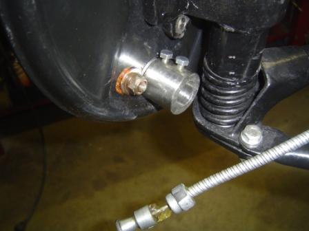
So I made a tube/bush with inside two different diameters, one matching over the brake mechanism, the other accepting the cable. So now everything is on the spot as original, but with a strong support from the outside. I made it with a small fixing bolt that clamps the tube on the brake mechanism, and another that blocks the brake cable once he is on his spot. So I can take it apart whenever I wanted or needed. And it seems to work perfect, the cable stays nicely where he has to be, doing what he have to do without jumping around like Michael Jackson in his better days.
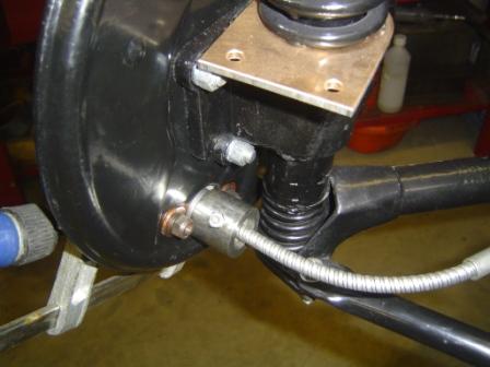
Problem solved I thought! Because then I discovered, when matching the new cables with the old originals, that they are on the LH side 25mm. too long, and on the RH side 25mm. too short. So I think but am not a specialist - that it is because mine is a LHD car, and the cables come from the UK and are for a RHD car.
So I carefully shortened the shell of the left brake cable, without touching the inner steel cable itself, until I had the same length as the old one. And on the RH side I made the cable longer by using a long (30mm) nut, connecting the new wired cable end with a stud I made from the old cable. Everything secured with Loctite to avoid loosening.
So now with the compensator in place, all fits well. And after I made a brand-new connecting rod between the brake pedal and the compensator, the braking system could be tested.
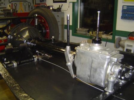
Then that I discovered that the rear brake cable, coming from the pedal an passing through the handbrake, is touching the gearbox. In fact he has done that in his previous living years so hard, that there is already a groove in the aluminium housing of the box. To risky to leave that, I dont want to brake one day, with a leaking gearbox housing as result. I find it rather strange, but things are what they are, and maybe all that was not so important in those days J.
So I made a spacer, that brings the whole handbrake mechanism about 12 mm. more out of the centre. And now the cable moves freely, just missing the gearbox. So my fear that on a good day braking would have cause a flood of gearbox oil in the car, has gone.
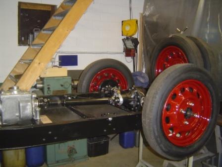
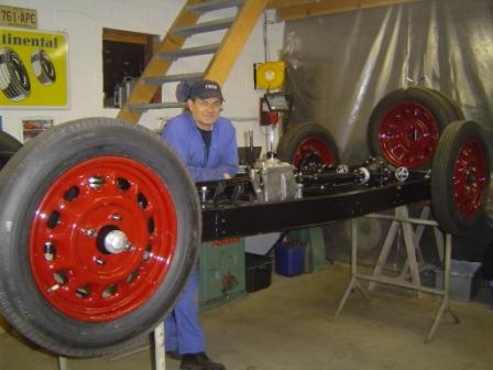
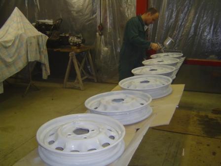
In the meantime I also had made a definitive choice about the future colour of the car. A burgundy chosen out of 6 colour tests I did. Too dark too light That it! And that mains that I finally could paint the wheels, and put the new tyres on. They look great, the rust damage is all gone, and the colour is even better than I hoped!
So now my next big job is finding a good steering box - mine is incomplete also I have to put my engine together, and find a solution for the radiator and radiator shell. That has to be re-chrome plated,but the radiator is fixed on it with tin.
The guys from chroming company looked at me as if I came from mars when a asked them if they could do that job, and in the radiator company they thought that I was joking
So a new and big challenge for 2012 Lets go for it!
It is December 2011 now, and my own imposed deadline to have a finished rolling chassis by New Year is nearby. In fact it is so close that I already decided for my own that it will be impossible to achieve my goal. A complete rolling chassis for me means that the whole running gear is on the chassis including the engine -and that it can be moved on his wheels. At this moment I hope that I can archive the greatest part of all that, but the steering box seems to be a big problem, and I still have to start working on the engine. So there will be no firework for me with new year L.
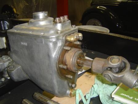
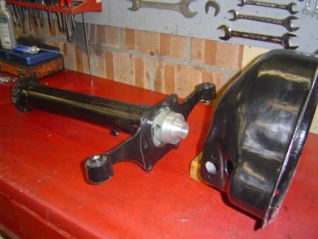
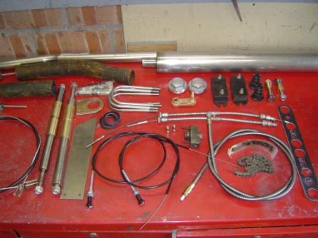
Since my last report I remade the prop shaft with new universal joints. It was a fairly simple job, because after some measuring - with some great help from my friends of Anglo Parts - I discovered that the ones for an MGB are a straightforward fit (www.angloparts.com).
In the meantime my son was taking care of the wheels. They where sandblasted, and then he sprayed several coats of filler in all the rusts damaged places, followed by sanding them down. And again, and again, until all the bad markers are gone He is very patient J.
I also did a close inspection of the inside of the gearbox, and it looks in almost perfect condition. So I just replaced the oil seals and one bearing, and I am pretty sure that will be enough. I also rebuild the rear brake adjusters and the pull system, and mounted the relined brake shoes. All necessary things before I could mount the rear brake cable and handbrake system.
But to find out how the cable system fits in the chassis, I was looking at the pictures I made at Georges workshop earlier this year. So I discovered that Istill had to make the floor boards and put them on their spot. The result was that I had to unbolt a lot of what was already in place, because with the gearbox an prop shaft in situ, putting the floorboards in is impossible. Even the rear springs had to be loosened on their front side.
So I bought a good quality 13mm. multiplex plate and made the floor boards, thereby using patterns I first made from cardboard. Then they received several coats of black paint, and we put them in place. In fact a fairly straightforward job, but still good for a whole day off work, not counting the time I will need to replace what I had to remove.
I always try to look far enough ahead to avoid being out of parts to keep the progress going, but in my young enthusiasm J forgot that I also have to look in what order the parts have to join the chassis. Seems all very logical, but when you have a project like this that arrived in cardboard boxes, its always a bit of a jigsaw puzzle.
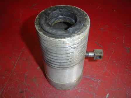
From that angle I looked a bit closer to what had to come, and repairing the clutch sleeve was one of the major things on the progress list. That part is located in a tube, bolted one side on the bell housing, other side on the gearbox. Inside there is a shaft connecting the outgoing movement of the engine to the gearbox, after the clutch. Simply said: engine > clutch > bell housing > between tube with prop shaft > gearbox > outside propeller shaft > differential/rear axle. As you can see, a nice piece of mechanic.
So to move on with mounting the drive line, until the point where the engine has to be bolted on, I have to make sure the whole clutch operating mechanism is ready. The between tube is bolted on the gearbox, and the handbrake mechanism is bolted on the between tube. And since it is a one cable system, I can never complete the rear breaking system without tube and gearbox in place.
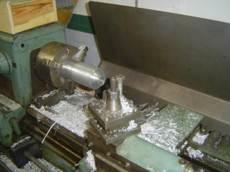
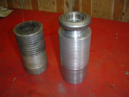
The old clutch sleeve has a completely worn out carbon lining, and I was not able to find a new one. But no problem, by my previous spy work I knew that it could converted to a more modern system, by using a roller clutch bearing. A bit searching learned me that the bearing of an MGB is perfect for the job. So I only have to make a new sleeve, accepting that part J.
My brother in law provided me with a 85mm. solid aluminium bar, and out of that we made a nice new sleeve on the lathe, with even the grease lines in it. It is made a bit longer than the old one, but that will be corrected after a try out. Because I am not 100% sure where to drill the hole for the pull eye of the clutch mechanism, that have to wait also until I measured everything by bolting it all together, measure it correctly, and then bring it to the right size. One or two extra hours work, but I cannot afford to take a guess, making that sleeve was a too big job. And beside of that, I dont have an extra aluminium bar J.
It is October 2011 now, and it has been a long time since my last progress rapport. The summer has ended now, but despite the bad weather in the last few months, I did not found much spare time to work on the Morgan. In the garden everything keeps on growing, and I had to cut and weed like a real professional gardener. And despite being a real petrol head, I far from hate that kind of work. It is something else, and gives me a bit of a green image, not bad at all
That in combination with maintaining my other cars summertime always means a lot of driving, good or bad conditions - as hold me back from making much progress on the series I project.
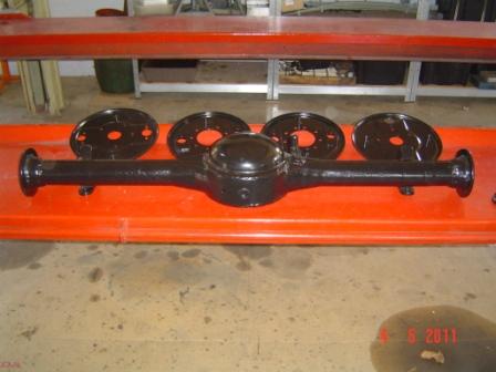
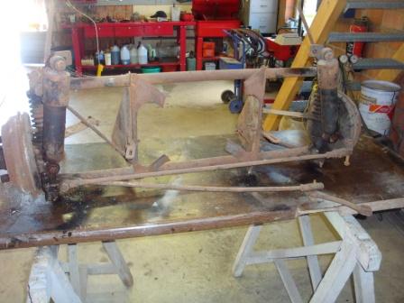
But still I did managed to have the front sub frame, and the empty banjo and rear springs back on their spot. I also replaced the ugly rear shock absorbers with the correct type of friction dampers. They were rather easy to find in the UK, although again not cheap. Since the old ones were non original, I did not had anything to match my pretty new ones with the chassis. So I hadto search for appropriate bolts, and make bushes to fix them properly. Thereby using the photographs I made earlier at Georges Proudfoods workshop as a guide.
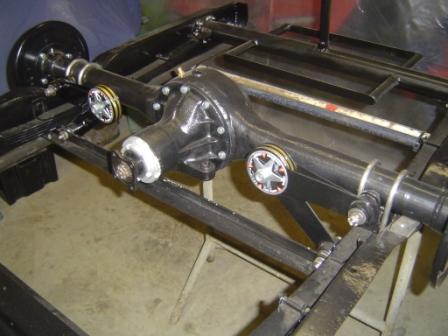
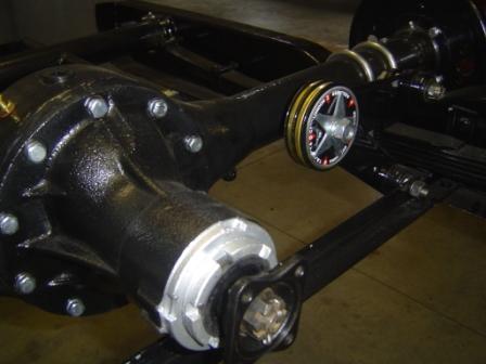
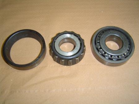
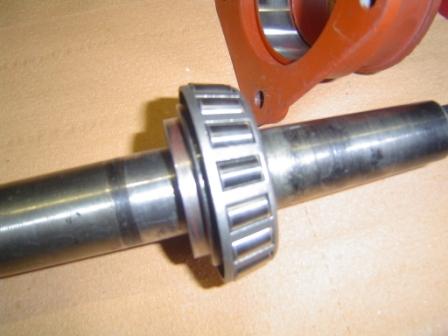
Next big problem to solve where the roller bearings for the rear axle. When I discovered they were covered with surface rust, I simply thought to buy new ones with the same number. But it turned out not to be that easy, because the original bearings are tapered on the inside, as is the axle. That makes that they are simply pushed on the axle, and stop on a certain pre calculated point. But soon I had to find out, that kind of bearings do not exists anymore
Plan B started I had to find a bearing with the same or about the same outside diameter, so the bearing housing could accept the cup without too much machining and/or lost of wall thickness. On the other hand, with an inside diameter not much bigger than the axle, but big enough to have space to accept a custom made conversion bush. I had to be a bush that catches the tapered axle inside, and accept the straight bore new bearing on the outside. Finding that bearing was the most easy part, I dived in the roller bearing catalogue, and bought an new set of bearings following the ISO standards. Outside almost a perfect fit, and inside with a diameter of 35mm.
After much thinking about how to handle, because the new bearings have to end on exact the same spot as the old ones, I measured the distance from the back of the original bearing in place, including the housing, to the top of the axle. I argued that if the housing came back on exact the same spot, the end position of the axles would be exact the same as original. So the bushes had to have another inside (tapered) diameter than the original bearings, because there has to be a stop collar of 3.5mm on the bush, to keep the bearings from moving forward in the direction of the differential. Since I had already 2 mm profit, being the difference in thickness between the old and new bearing, I only had to move a little bit forward on the axle to catch the extra 1.5 mm finally required. Easier said than done, in fact for me not an easy exercise.
But help came in the person of Kurt, son of a good friend, and a very modest but clever technical engineer. Above that he is a real classic car lover, what makes the perfect combination. We discussed my solution, and we reached a consensus, we measured and measured again.
Then, he took a piece of paper and his portable Japanese brain. After a minute OK maybe two - he came with the angle that had to be used for the inside of the bush, just as simple as that. For me Chinese and Russian together, for him a fairly simple calculation
So once again that proves my parents were right when they told me ages ago not to quit school to early, and go for some extra years and an higher degree. But that motorcycle was so exiting, and the girls were so pretty Or was it the other way around? By now it is so long ago that I cant remember
Finally Kurt presented me to make the bushes on the lathe. I had no objections at all, because despite all the right calculations, make a tapered inside in a bush is easier said than done. So when they were ready, the great moment to try them out the axles has arrived. The new bearings where pressed on the bushes, for extra safety sealed on them with Loctite, and tapped on the axles.
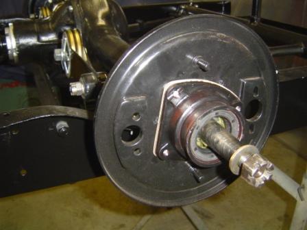
I placed the differential back in the banjo, and pushed the axles in. Then I bolted the brake back plates and bearing housings on, thereby re-using the old shims to adjust the correct lateral play as a test. It came out that I just had not enough play, the axles turned, but a little bit too heavy. So I made two extra shims, simply in sealing paper of 0.40mm. A perfect fit with the correct amount of free play was the result. I have to say correct because my very summarily workshop manual stated allow a little play. So how much is a little? I presume almost 1 mm will do.
So I took what I have as being correct, and moved on. Loosen everything back, the axles out, new oil seals in, and the whole circus back together. It looks and feels very good, so I am proud of the result. Now I can start on the rest of the rear axle, brakes and braking system. Easier said than done because of the cable braking system, but I look forward to move on.
With an extremely early and sunny spring in Belgium, I have a lot of work to do outside the house, so the Morgan project is a bit staggering. Thats the price one have to pay for living more in the country, in a house with a nice workshop in the backyard, but also with a big garden around it. But still I try to do some things that are progressing the restoration in their own way. A continuous search for parts and technical advice on the internet is one of those things. Looking forward to have some things ready to make reassembling in the future more easy, is another. So I took the front cross member, the empty rear banjo axle, and the brake anchor plates to the powder coat company, to give those parts a nice black jacket. It would take a week or two to have them back so they said, but that was no problem at all, I even found that fast.
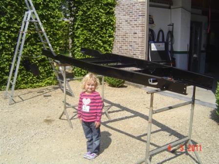
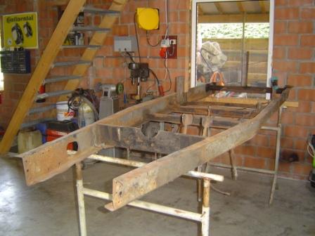
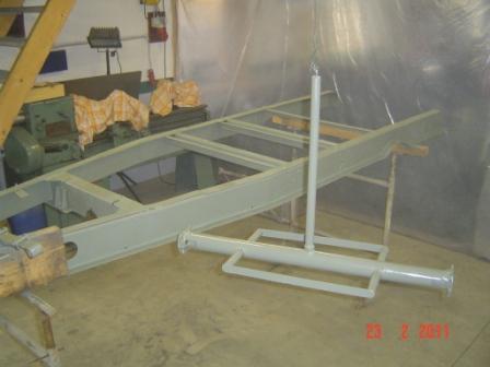
But every time I walk in to my workshop, I have the feeling that the chassis looks at me and screams paint me paint me, I will look so much better afterwards. I could no longer resist on that cry for help, and on a sunny Saturday I decided to lay it out in the sun, and give it a go.
My choice is to go for a two pack black chassis paint, as I always used by my other restorations in the past. I think that is a good basic paint, and I like working with to the pack system. Nice, fast, and with a great finish, what do you want more? So after some sanding down to give the paint a better grip, I sprayed first the underside of the chassis, and turned it after 30 minutes so I could do the top side. And yes, it looks better in black, although I think that the green undercoat was no bad at all. Even my youngest granddaughter found it ok, and she is a very critical judge
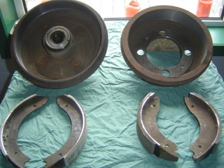
I also took the brake shoes and drums to a guy that I know for some times, and that used to work in a car parts company that also provided brake relining services. When the company stopped about two years ago, he simply bought all the machinery and had it installed at his shed in the backyard. And now he does brake relining for friends and acquaintances, just as a hobby. Yes I know and admid, I have some strange friends
But anyway he did a great job, relining the shoes and having the brake drums rectified. Also parts to put on the shelf for a while, until things are ready to be reassembled, but it gives me a good feeling to know that some pieces of the puzzle are already done.
But the best move I made by far was to contact George Proudfoot in the UK. I been told that he was definitely the man with the most knowledge about Morgan series 1 in the world. And he also runs the MSCC series 1 spares department, so I hoped to buy some necessary parts for my restoration from him. But it was not easy to find a date that suited both of us, phone call after phone call followed, but finally we made an appointment for Friday the 13e For superstitious people real horror, but for me a very good choice. Now I could combine that with the Beaulieu Spring Autojumble, because the motor museum is only about 30 minutes from where George lives.
Visiting George has been a (great) experience on its own. He is a charming helpful man, and he really knows everything about the subject. A series 1 encyclopaedia on two legs, packed with good advice and some amazing tips and tricks. The work I saw from him on a few cars that were in his workshop, made me realise that despite my experience with restoration projects, I still have much to learn. Great respect man!
I had a lot of old parts with me that I had to re-use, and for a lot of them I needed his advice. No problem at all, with patience and experience he has gone thru the whole pile of junk with me. And then as a cherry on the cake, he provided me with a lot of otherwise nearly not to find parts. It has made my day and the displacement to Fareham really, really worthwhile. Again, thank you George!
The next day I had a good English breakfast at the hotel, and was rather early at the autojumble. But that gave me the time to search and find a lot of useful parts, and that turned out to be mostly electrical parts for use in the end stadium of the project.
But if there is one thing that I learned from the past, than it is, if you see something on a jumble that you can use: buy it! Later on can be never again, and than your stuck with the stupid feeling if I had So when I returned to Belgium in the late afternoon, it was with a very good feeling and an empty wallet. Happiness can be simple to archive .
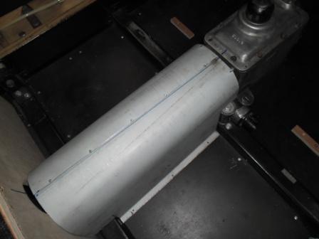
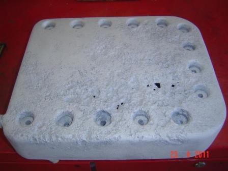
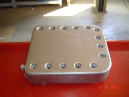
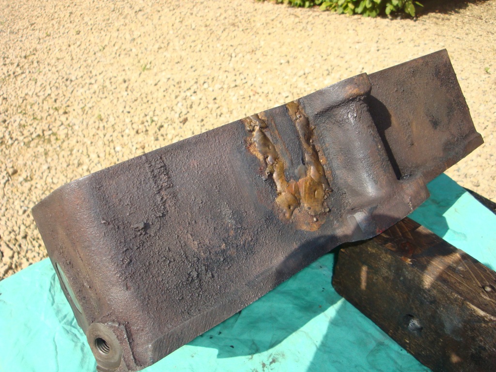
As I mentioned in first things first, the oil pan is badly damaged by corrosion. And since it seems to be almost impossible to find a replacement, I had to be inventive about repairing the one I got. Repairing seems to be the only choice, simply because the price quotes that I got to cast me a new one were too high. High but perfectly understandable, because all that work to make just one example, makes it extremely expensive.
So my first thought was to have it welded by a specialists firm, but my Australian connections advised me not to do that, because of the poor quality of the aluminium. And when I had a good look at it, I could do nothing else than agree with them, that aluminium looks more like gingerbread than metal. They told me to use some modern epoxy stuff to repair and even rebuild metal parts, rather than taking the risk of burning even bigger holes in the pan, trying to have it welded.
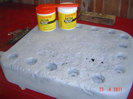
So I contacted my colleagues at work from the technical department (I work for the Flemish public transport company De Lijn) and asked them what they could advise. After some thinking they came with Locktite Hysol 3475, a two pack aluminium epoxy, as the ultimate solution. To be absolutely sure that it would be oil and temperature proof, I contacted the Locktite helpdesk, and they agreed with my colleagues advise.http://www.loctite.be/cps/rde/xchg/henkel_bef/hs.xsl/3888_BEF_HTML.htm
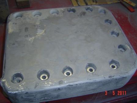
They were very helpful and even phoned me a few days later to give me some extra tips and tricks, so I started to work. First I had the oil pan slightly sandblasted to give the product a better grip, and then I used it further completely by the book. It was very easy to use, and gave directly a good feeling about the end result. A satisfying result that I became after 3 thin layers of product, slightly sanding the stuff between every layer. Take it slow but perfect, rather than trying to do the job fast and in one movement. Once the outside was finished, I added as an extra a thin layer by brush on the inside of the pan. Just to insure that it would be leak proof.
Afterwards I made it all straight with some abrasive paper on a wooden block, and sprayed aluminium paint on it. The result looks very good and perfectly usable, if it not leaks... So as the ultimate leak test I filled it half with white spirit, left it in for a week, and it has lost nothing. So I think the result is OK!
To keep things going on, I think It is time to inspect the chassis on cracks and bends, and repair what I already can see. Yes, I like to do that before it goes to the sandblasting company, after the sandblasting process I still can look at the minor faults, and repair them at that moment.
Fortunately after a close inspection, I discover that the general state off the chassis is not so bad as I thought. It has only surface rust, so there are no parts to be welded in. An on the field of cracking, It is a cold riveted chassis. And I am always told such chassis can work, and because of that they dont crack. True or false? I dont know, but I am willing to believe it, looking at the state of this chassis # 1861.
The worst damaged are the fixing points of the rear springs. Where the bolt goes thru the chassis, it is not an round hole anymore, but a buttonhole. I repaired it by welding a thick washer on both sides of the chassis, so now it is three times thicker than it was originally. I think that will do the job for another 50 or 60 years.
Another small problem is the tube between the two spare wheels, for the bolt fixing the spare wheel clamp. Somewhere in the past it has been cut in half. Maybe the needed a piece of tube to repair the central heating? Anyway, I put the tires on their place and measured the high required. Then made a new tube, 5 centimetre shorter than the complete high, and with a nut welded in. Simple, and but since I have to make the fixing bolt also, this should work. For the rest I reinforced the welding of the transverse bar holding the pedal assembly. And then the chassis looks good enough to be sandblasted.
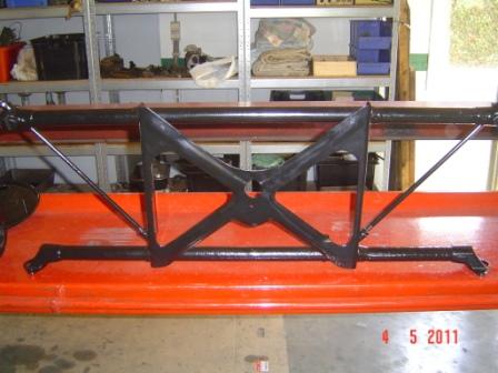
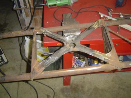
The sub frame for the front suspension requires more attention. It has major cracks and it is bend a little. And the cross that is in the centre, and responsible for the strength of the sub frame is simply cut out.
Why it has been done I dont know, maybe to take out the engine? But no panic, I still have some old iron on surplus from the rusted Austin Healey that I broke down to restore mine. And AH uses a cross almost similar to that from my Morgan. So after some cutting and welding, I have a sub frame that looks like it has to be.
Now I have to straighten the LH tubes and repair the cracks where they are welded on the middle section. To reinforce the transverse tubes, I made some extra inner tubes from central heating pipe. I made them on measure on the lathe, and now they slide just into the original ones. After that I MIG welded everything, so one Sunday morning solved the whole sub frame problem. Now I still only have to make a new tension rod for that left side, and the sub frame is ready to be painted.
So with the major problems already fixed, the chassis and some other parts are loaded on the trailer, and went up to the sandblaster. I also took the oil pan with, to have it (more gently) sandblasted, so I can have a good look on the corrosion damage, and decide what to do with it. After a week the chassis was back, and al lot cleaner.
After a close inspection I could find othing special, only some little cracks that are welded in a second. So finally I can paint the chassis in wash primer, to prevent it from surface rusting in the time I need to fix the other parts that are needed to come to a rolling chassis.
When the whole lot, or most of it is ready, I will follow the prophetic words of the Rolling Stones, and PAINT IT BLACK !
With the chassis now in clear sight, I have to think about some kind of strategy around the rebuild. Starting a work like this without a good plan is plain madness. I risk to end up with a lot of wasted time because of the difficulty of finding parts or craftsman to do some specialized work for you is real. On the other hand, waiting is a part of the restoration process
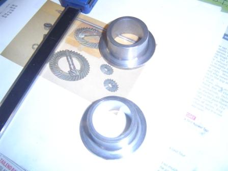
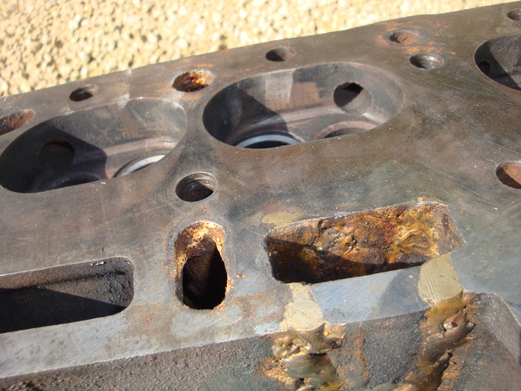
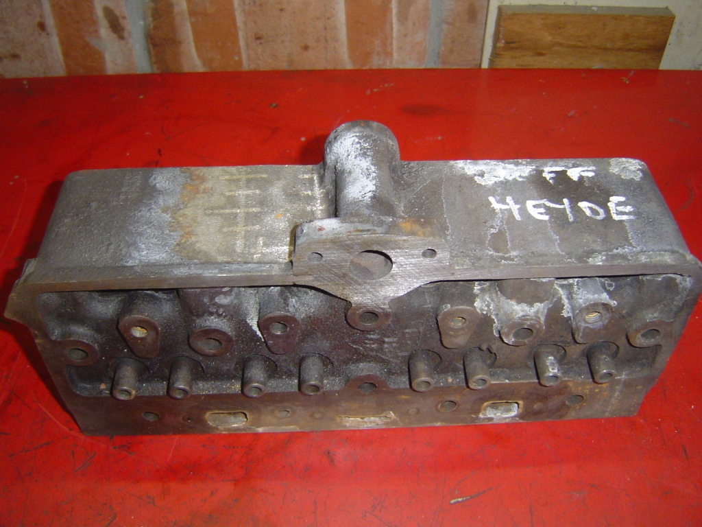
First thing to decide is the way I will go with the chassis, concerning the engine. The original block is ready, but for the moment thats all. The cylinder head has been frost damaged, and had a bad repair in the past. Since it is a head specially made by Morgan, a OH conversion of this type of Standard engines, it is not simply a matter of buying another one. Also the aluminium oil pan, for as far as I know also unique for this MOG engines, is damaged by corrosion. It seems to be that the engine has been standing on moist ground next to the car, in the years before Jean found it. A badly corroded oil pan is the tragic result.
So as a possible solution, I bought about a year ago the engine and gearbox of an MK II Ford Escort. With little changes to the MOG chassis, that must be suitable to build in temporarily in the project. Just to speed things up a little, and to get the car earlier on the road. The correct engine can still be fitted afterwards, once it has been finished. But on the other hand, long-time experience learned me that such solutions mostly are crap. Once the car is running with the donor engine, the chance of being reunited with his correct engine is very little.
So after a bad night sleep I decided to go for the hard way, that is with the original engine and gearbox. I have the correct parts, so I strongly think thats the best solution, and because there is only one proper way to restore a car: Original, or as close as possible to that. It will probably set me more than a year back, but as I already wrote, I am not planning to die in the next years, so time is on my side.
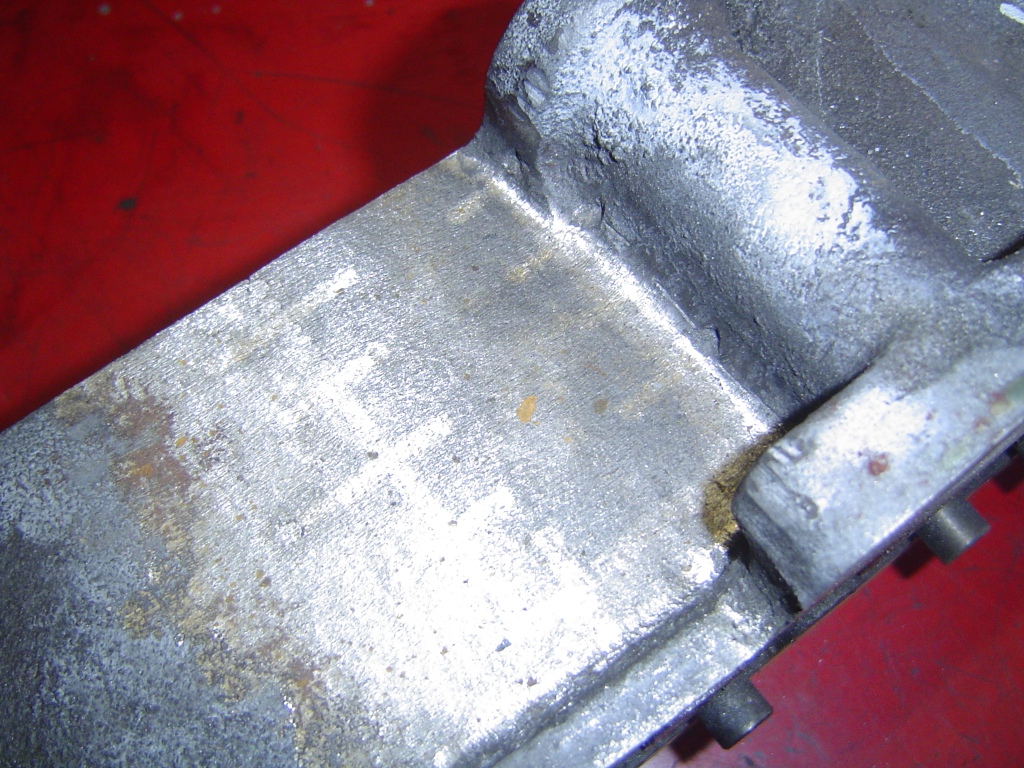
My first concern then was the cracked cylinder head, who was going to repair that in Belgium in a proper and reliable way? I have no idea. But in England there must be specialists for such a job on every corner, that can be no problem And because the biggest auto jumble is on the calendar for 11 and 12 September 2010, we go over there. Only for one day, because before I had no such plans, and finding a place to sleep on such a short notice can be forgotten. So on Tuesday we decided to go. Me my son a good friend, and my brother in law. The next Sunday morning at 04:00 am we were on the road. Beaulieu here we come!
Huge, thats all I can say about the auto jumble at Beaulieu, all other words are too little, to small You have to have a good plan, and about ten eyes to see a bit of all that is there. In that way you only miss the half, the other half you can keep for next year But despite such massive supply of parts and services, finding someone to repair a cracked cylinder head like this in a proper way was not so easy as I thought.
After seen about the half of the field, I was getting a bit desperate. Until in the late afternoon a Belgian friend we stumbled on, tipped me about Nick Hood from Surelock casting repairs. We managed to find his trade stand, and I showed Nick some photos of the cracked head. After taking a good look at it, a simple smile and yes I can do that was the answer. What a relief... http://www.castingrepairs.com/ So we went quickly up to our car to get the damaged part, and left it with Nick to be stitch repaired. By Christmas he sayd it should be ready, and that was all fine by me
So my major mission of the day was accomplished, from now on I could browse relaxed around the field and dream a bit about the further order of the restoration. My next big concern would be the oil pan, but I hope that is not gonna be the worst part. Once those to two major parts are back in shape, I can reassemble the engine and start thinking about the carburettor and ignition. Also tricky parts, but they are all in my pile off boxes, and looking repairable. It surely will take some time to find the right replacement parts, but it must be possible. And in the meantime I can start working on the chassis.
And after a good pint or two, my straight plan took more and more shape: having a rolling chassis by the end of 2011. Do I grab to high, or is this wishful thinking? Only time will tell
In the following months, a lot of maintenance on my other cars kept me from start to work on the MOG chassis. But smaller things like disassemble the drive train, the rear axle, and repairing the support for the spare wheels, has succeeded.
And then around half December came a phone call from Nick: the cylinder head is ready, pressure tested and all! As he had promissed, in time for Christmas. The repair was not really cheap, but on the other hand, good work never is. And when it arrived, the quality of the job surprised me. The guarantee Nick gave me on the repair will be long gone before I start the engine for the first time. But I am strongely convinced that the guarantee wont be needed
Next step now is completing the cylinder head, by grinding the valves and seats, and putting it all together. That work will be done by my friend Eric. He has the skill, the tools, and the machinery to do so, that will be fine.
In the meanwhile I try to find out what colour the engine must be painted in to be correct (if you know, mail me!). Than trying to find a sound oil pan (mine is really bad, if you have one, mail me!) and off course to go on with the chassis. Because now I have a deadline to catch !
It must have been 1970 when Paul, a bartender in a local club in Mechelen (Belgium) who was driving an MGB at that moment, woke up my interest in sport and classic cars. He had a collection of old cars, most of them British and dating from 1930 till ± 1960. One day he appeared in a 1952 flat rad Morgan he bought around Antwerp. Until then, I never heard of Morgan before. But when I saw that car in burgundy with black wings, I was hooked for life. I was 18 than, very enthusiastic, and with only one small problem: money
But things got better, and in the mid 70's I made my first steps in the classic car world. In an early MGB, and until today I still think that is the right choice for a beginning classic car enthusiast. Later on, more MGs Triumphs - Austin Healey and Jaguars came and went, all with their own ups and downs. But no matter what, British cars have always been my favorites, and they still are. Years and cars went on, but with the past in mind, I always kept one mark above them all: MORGAN. Simply because of its authentic looks and charisma, for me still the real thing ".
So when Jean, a good friend, in 1983 traced a Morgan series 1 in Brussels, and rescued the car from demolition, for me the Morgan madness really got started. I nagged him the ears of the head to sell me the car. But nothing helped. He was planning to restore the Morgan itself as a present for his wife, so she could drive it on classic car meetings. But I got the promise, that if he would not implement the restoration, I would be the first one having the chance to buy the Morgan.
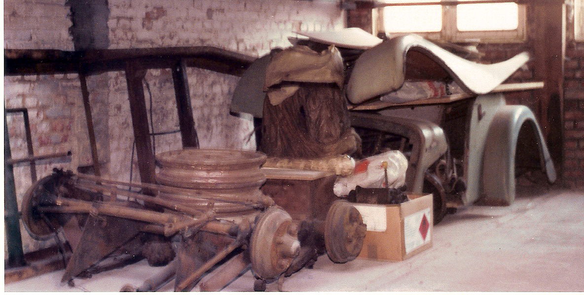
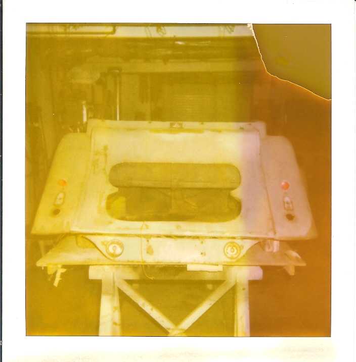
And yes, people with a word of honor really exist. In 1990 we saw each other briefly at a classic car show. He asked me almost casually if I still wanted the car, and a simple yes among friends was enough to make my dream come true. Finally it happened! Exactly one week later I went to collect the car, or what had become of it. Now the Morgan 4/4 was completely in bits and pieces, and stowed away in boxes. The chassis was hanging on the ceiling, the two halfs of the body on the wall.
Fortunately for me Jean is a talented technician, so not of that "in boxes thing" was a problem for me. The car might have been dismantled, but is was done with logic and sense, I was sure abouth that. And on the other hand, he had some things already done in his own perfectionist way. The engine block was overhauled, the dashboard and gauges were very professionally rebuilt, and a correct set of 6 brand-new tires was also present, among some other small parts.
Up on arrival with my treasure at home, my neighbor asked me if I was starting a old iron business... I told him to start a carreer as stand up comedian. He is not really that funny, so he helped me to unlood the trailer, and after that everything was neatly inventoried and locked away. It had to wait a little bit, because I still had an MGA 1600 to restore for my wife. And MGB for my son.. And after that a Triumph TR 3 that I owned since 1975... Because I realized that the restoration of the Morgan would not be for the near future, in 1996 I bought me a metallic gray 4/4 from '76. So with the Morgan virus re-injected, things would speed up I thought. But then came a lot of alterations to the house, followed by the restoration of an Austin Healey 3000. Later on we moved to a larger house because I needed more space And then out of the bleu a nice Jaguar MK II crossed my path, with of course some minor work on it. And before I knew, it was 2010
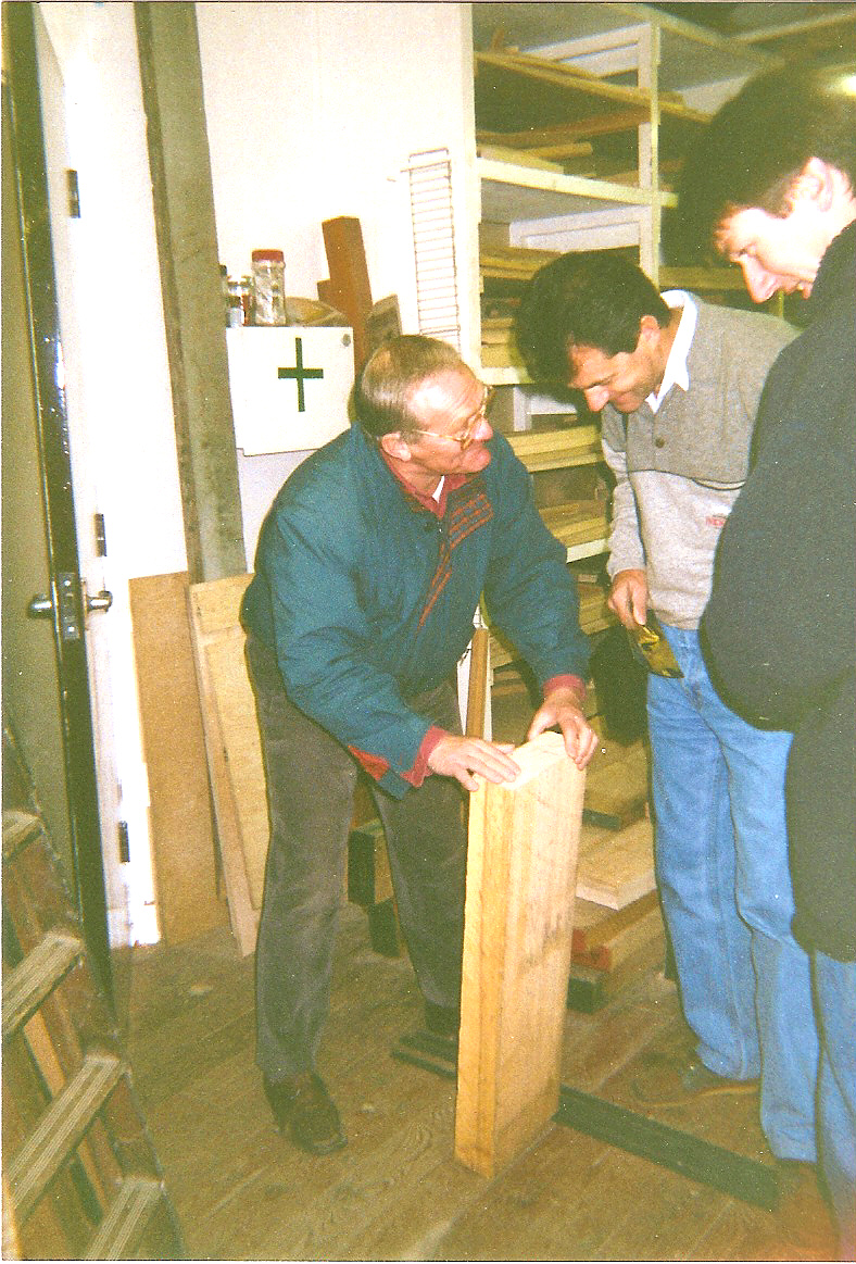
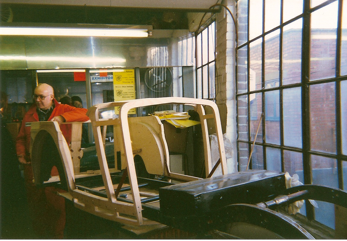
But fortunately, in the meanwhile I had the great idea to have me build a new skeleton body for the Morgan. Simply because on the 1996 MGCC Silverstone gathering I met two older gentlemen who were engaged in the manufacture of body's for pre war MG's. Two fantastic craftsman who were willing to build me a brand new body, a Morgan was a challenge for them. They were both along in years, so I realised I could not postpone the job for years. That was the little pressure that I needed to act immediately!
We made a shortbreak to England with some friends, just for fun, and to deliver the remains of what was once a wooden frame personally in Newcastle upon Tyne. John and Roberts workshop Ashframes International, was located above a local garage. Fully stuffed with machinery, wood, and craftmanship. They used a winch to hoist up and down al what they needed or produced, by a hatch in the floor. Unthinkable for us here in Belgium, but at that time just simple and normal for them.
The agreement was that they would bring my newly made body to the next MGCC Silverstone gathering, and so it happened. In June 1997 the wooden body was brought home by a friend with a little van. It was tucked away in a safe and dry spot, and there it stayed, and still is Just on another more spacey location because of the change of residence, and with a little more dust on it.
So a few months ago, with the ugly number 6 comming in sight in front of my age (altough still 2 to go), I decided I dont have half a life resting to start and complete the restoration. Not that I am planning to die, o no far from that, but I am a bit worried on the practical part of getting in and surely out the car on a minor flexible age...
So in juli - yes 2010 - we decided to take the chassis of the wall, and move it to a good spot in my workspace. There is much thinking and planning ahead, but Finally after 20 years the restoration has started!
Welkom op mijn blog. Een blog die als alles goed gaat, na verloop van tijd aan mijn vrienden en bekenden een mooi overzicht zou moeten geven betreffende de restauratie van mijn Morgan series I. Ik hoop ook dat er na verloop van tijd wat reacties zullen op komen van mensen die met een gelijkaardig project bezig zijn, want erg veel informatie is van dit type wagens niet te vinden.
Voorlopig is er nog vrij veel dat ik kan plaatsen, omdat er een achterstand op berichtengebied in te halen is. Maar naar de toekomst toe zal er minder frequent nieuws te rapen vallen, gewoon omdat de restauratie nu eenmaal geen fulltime job maar een hobby is. Het werk zal dan ook niet altijd even snel vorderen, maar ik doe mijn best!
Na deze intro schakel ik over op Engels als voertaal voor mijn blog. Dat om een welbepaalde reden, het internationale aspect. Ik hoop om via deze blog in contact te komen met collega liefhebbers die me kunnen bijstaan in mijn zoektocht naar informatie, fotos en onderdelen. En al zal mijn Engels niet steeds even correct zijn - ik ben ook maar een autodidact op dat vlak - zal ik er alles aan doen om mijn taal van Shakespeare op deze manier bij te schaven, zo vang ik twee vliegen in één klap.
Veel plezier met mijn blog "Morgan series 1".
Jeff
Welcome to my blog. A blog that, if all goes well, after some time should give a nice overview on the restoration of my series I Morgan. I also hope that some reactions will come from people how are undertaken a similar project. Maybe we can help each other, because a lot of information on this type of Morgan cannot be found.
At the moment there is pretty much that I can post because there is a lot of old information that can be told. But in the future my posts will be less frequent, simply because the restoration is not a full time job but a hobby. The work will not always go quickly, but I do my best!
And though my English is not always correct - I'm an autodidact in this field - I hope it will improve my skills in the language of Shakespeare. Then I catch two birds with one stone, and that will be fine.